Printing and dyeing equipment with uniform dyeing
A kind of printing and dyeing equipment and uniform technology, which is applied in the field of printing and dyeing with uniform dyeing, and can solve the problems of affecting product quality, dyeing liquid pollution, uneven dyeing, etc.
- Summary
- Abstract
- Description
- Claims
- Application Information
AI Technical Summary
Problems solved by technology
Method used
Image
Examples
example 1
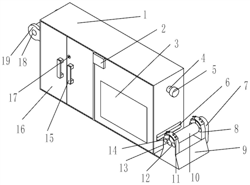
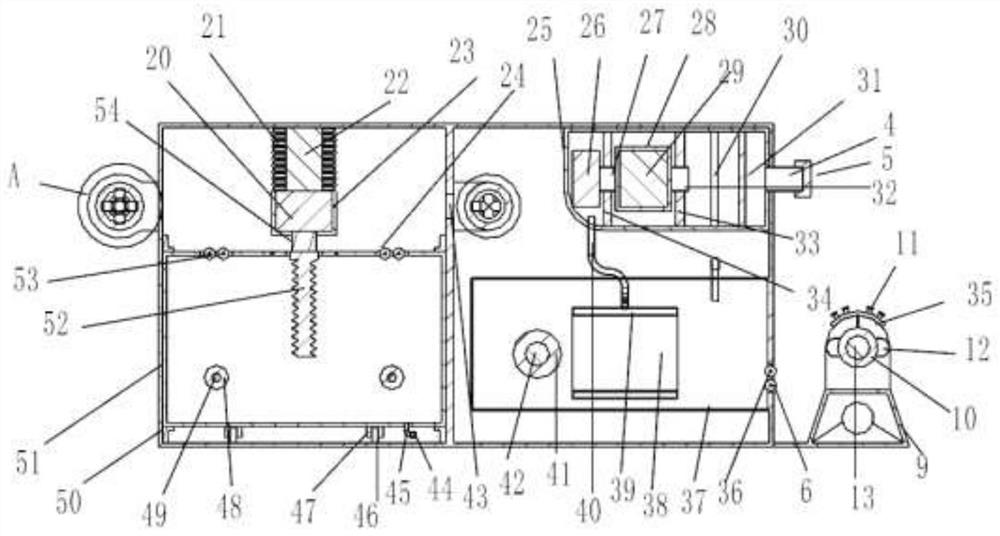
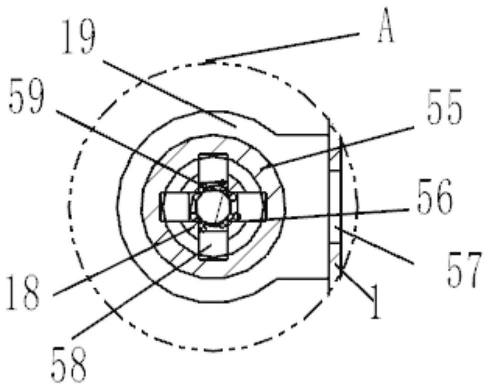
[0030] Example 1 has illustrated the concrete structure of a kind of printing and dyeing equipment with uniform dyeing, with reference to the attached Figure 1-8 , a kind of printing and dyeing equipment with uniform dyeing, including a box body 1, a dye box 51, a box room is opened inside the box body 1, a telescopic protective cover 21 is fixedly connected to the inside of the box body 1, and the bottom of the telescopic protective cover 21 is fixedly connected There is a protective cover 23, the inside of the telescopic protective cover 21 is fixedly connected with a waterproof electric push rod 22, the lower end of the waterproof electric push rod 22 is fixedly connected with a first motor 20, and the output end of the first motor 20 is fixedly connected with a first rotating shaft 54 for protection. The lower end of the cover 23 is fixedly connected with the water stirring blade 52, and the outer side of the water stirring blade 52 is fixedly sleeved with a bearing 74, ...
example 2
[0032] Example 2 has illustrated a kind of dyeing concrete structure of evenly dyed printing and dyeing equipment, with reference to the attached figure 1 , attached figure 2 , attached image 3 , attached Image 6 , attached Figure 7 , including a box body 1 and a dye box 51, the inside of the box body 1 is provided with a box room, the inside of the box body 1 is fixedly connected with a telescopic protective cover 21, and the bottom of the telescopic protective cover 21 is fixedly connected with a protective cover 23, and the telescopic protective cover The inside of 21 is fixedly connected with a waterproof electric push rod 22, the lower end of the waterproof electric push rod 22 is fixedly connected with a first motor 20, the output end of the first motor 20 is fixedly connected with a first rotating shaft 54, and the lower end of the protective cover 23 is fixedly connected with a stirrer. Water blade 52, the outer side of stirring water blade 52 is fixedly sleeved...
example 3
[0034] Example 3 has illustrated a kind of cloth drying concrete structure of uniformly dyed printing and dyeing equipment, with reference to the attached figure 1 , attached figure 2 , attached Figure 4 , attached Figure 8 , the inside of the box body 1 is fixedly connected with a hot gas box 25, the right side of the box body 1 is provided with a circular groove, the right side of the hot gas box 25 is fixedly connected with a suction pipe 4, and the outside of the suction pipe 4 is fixedly connected with a filter plug 5. The left side of the suction pipe 4 is fixedly connected with a hot gas box 25, and the inside right side of the hot gas box 25 is provided with a filter chamber 31, and the inside of the filter chamber 31 is evenly and equidistantly fixedly connected with a filter plate 30, and the left side of the filter chamber 31 The side is fixedly connected with the first sealing plate 33, the inside of the first sealing plate 33 is provided with a circular groov...
PUM
 Abstract
Description
Claims
Application Information
 - R&D
- Intellectual Property
- Life Sciences
- Materials
- Tech Scout
- Unparalleled Data Quality
- Higher Quality Content
- 60% Fewer Hallucinations
Browse by: Latest US Patents, China's latest patents, Technical Efficacy Thesaurus, Application Domain, Technology Topic, Popular Technical Reports.
© 2025 PatSnap. All rights reserved.Legal|Privacy policy|Modern Slavery Act Transparency Statement|Sitemap|About US| Contact US: help@patsnap.com


