Fuel feeding device of engine

A fuel supply device, engine technology, applied in the direction of fuel injection device, engine components, engine control, etc.

Inactive Publication Date: 2003-11-12
HONDA MOTOR CO LTD
View PDF1 Cites 0 Cited by
  • Summary
  • Abstract
  • Description
  • Claims
  • Application Information

AI Technical Summary

Problems solved by technology

However, in the above-mentioned conventional fuel supply device, the fuel suction port opens toward the downstream side of the flow direction of the air flow in the intake passage, so it is difficult to say that the fuel atomization in the air flow is good. In order to further reduce fuel consumption, improve exhaust performance and Engine output power, hoping to further promote fuel atomization

Method used


Image

  • Fuel feeding device of engine
  • Fuel feeding device of engine
  • Fuel feeding device of engine

Examples


Embodiment Construction

[0020] Next, embodiments of the present invention will be described based on the embodiments of the present invention shown in the drawings.

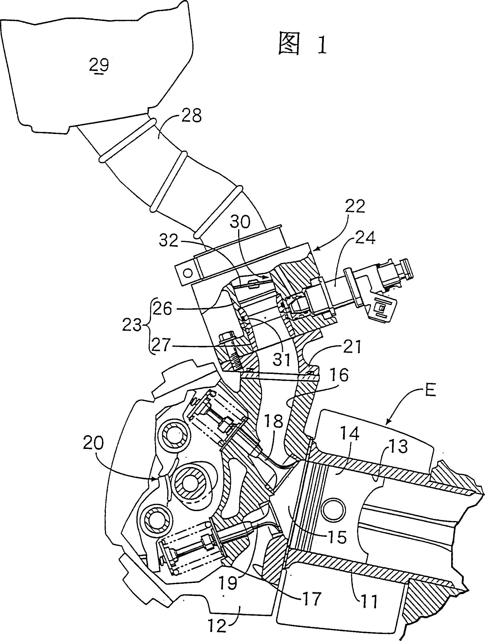
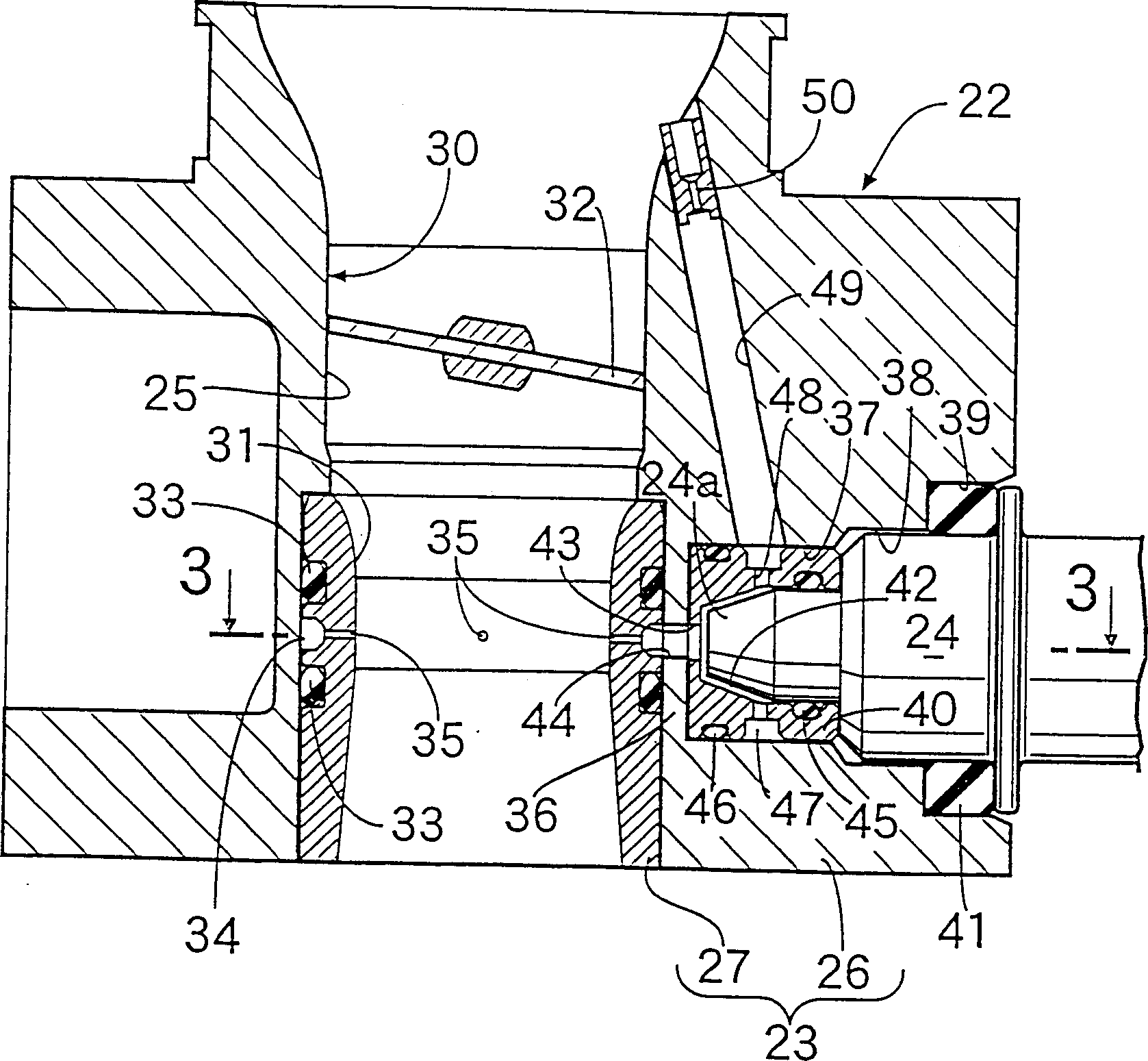
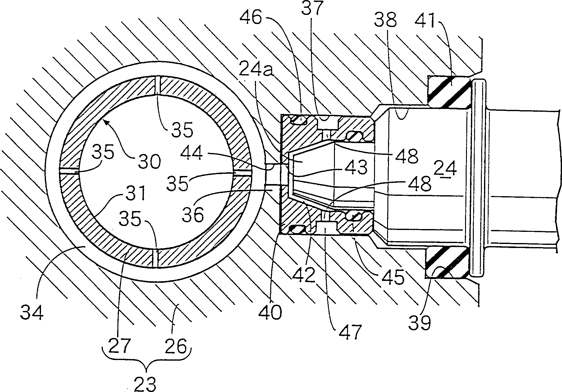
[0021] Figure 1~ Image 6 Showing the first embodiment of the present invention, Fig. 1 is a cutaway side view showing the intake system of the invention, figure 2 is the enlarged longitudinal section view of the intake channel forming body, image 3 for figure 2 A 3-3 line cross-sectional view of the, Figure 4 is a graph showing the relationship between fuel supply pressure and exhaust performance, Figure 5 is a graph showing the relationship between fuel injection timing and exhaust performance, Image 6 is a graph showing the relationship between net mean effective pressure and exhaust performance.

[0022] In FIG. 1 , the engine E has a cylinder block 11 and a cylinder head 12 joined to the cylinder block 11 , and a combustion chamber 15 is formed between the piston 14 and the cylinder head 12 , and the piston 14 is slidably ...


PUM


Abstract

The invention provides an engine fuel supply system, in which a fuel injection valve is fitted in an intake path organizer forming an intake path communicating with an air cleaner. The intake path organizer has a fuel passage for guiding fuel from the fuel injection valve, a fuel induction port having one end communicating with the fuel passage and the other end communicating with the intake path, and an air bleed passageway having one end communicating with the intake path further upstream than the fuel induction port and the other end communicating with the fuel passageway. A fuel induction port 35 opens to an intake path 30 in a direction orthogonal to air flow circulating in the intake path 30.

Description

technical field [0001] The present invention relates to a fuel supply device for an engine. The fuel supply device is provided with a fuel injection valve on an intake passage forming body forming an intake passage communicating with an air filter. An outlet, and an air discharge passage, the fuel passage guides the fuel of the fuel injection valve, the fuel suction port communicates with the fuel passage at one end and communicates with the intake passage at the other end, and the air discharge passage is at the end of the fuel suction port The upstream side communicates one end with the intake passage and the other end with the aforementioned fuel passage. Background technique [0002] Conventionally, such a fuel supply device has been disclosed in, for example, Japanese Patent Laid-Open No. 5-26132 and the like. [0003] However, such a fuel supply device sucks the fuel supplied from the fuel injection valve by the air flow flowing through the intake passage to atomize i...

Claims


Application Information

Patent Timeline
Patent Type & Authority Patents(China)
IPC IPC(8): F02M69/00F02M35/10F02M69/04F02M69/32
CPCF02M69/043F02M69/047F02M69/325F02M35/10216F02M35/10118F02M69/042F02M35/10085F02M69/044
Inventor 上田稔池田健一郎
Owner HONDA MOTOR CO LTD
Why Eureka
Try Eureka