Novel bus relay

A relay and bus technology, used in relays, circuits, electrical components, etc., can solve the problems of long opening and closing time of relays, affecting the safety and stability of relays, harmful arcs, etc., to avoid arcs and output voltage instability, It is convenient for distributed installation and ensures the effect of effective suction

Inactive Publication Date: 2016-03-02
成都霍睦斯电气有限公司
View PDF5 Cites 1 Cited by
  • Summary
  • Abstract
  • Description
  • Claims
  • Application Information

AI Technical Summary

Problems solved by technology

[0004] Domestic relays mainly have the following problems: 1. They do not have intelligent protection functions. When the load is short-circuited or the current is overloaded, the relay is still operating, which will cause damage to the device to a certain extent; 2. Generally, domestic relays use an integrated Installation, which makes installation, commissioning and maintenance very troublesome, and wastes a lot of unnecessary manpower and material resources; 3. When the high-current and high-voltage relay is working, the inductance charging and discharging effect of its driving coil is more obvious, which may cause the relay to turn on and off The time is long, and the metal shrapnel contacts are prone to harmful arcs during the transition from the closed state to the open state. When opening, the output voltage fluctuation may also be caused by the mechanical bounce action of the shrapnel, which will affect to a certain extent. The safety and stability of the use of the relay; 4. In daily work, due to the insufficient voltage of the relay coil, the generated magnetic force is small, and the main contact often jitters, and if the current passing through the contact is large at this time, the main contact dots are prone to sticking
[0005] The bus relay whose domestic application number is CN200610021741.3 alleviates the above problems to a certain extent, but many fundamental problems have not been solved. Therefore, there is an urgent need for a new type of relay that is easy to install and debug, and has higher stability and safety. bus relay

Method used


Image

  • Novel bus relay
  • Novel bus relay
  • Novel bus relay

Examples


Embodiment Construction

[0024] specific implementation plan

[0025] The present invention will be described in further detail below in conjunction with the accompanying drawings and preferred embodiments.

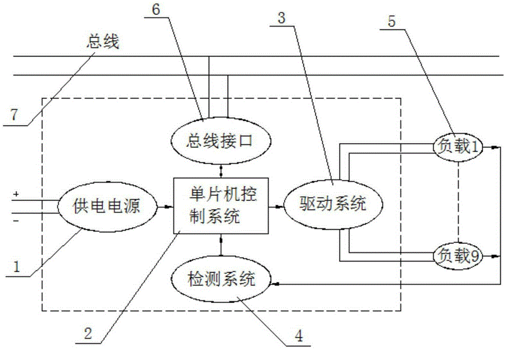
[0026] figure 1 It is a structural schematic diagram of a preferred embodiment of the novel bus relay provided by the present invention, such as figure 1 As shown, a novel bus relay includes a power supply 1, a single-chip microcomputer control system 2, a drive system 3, a detection system 4, a load 5, a bus interface 6 and a bus 7, wherein the bus 7 passes through the bus interface 6 and the single-chip microcomputer control system 2 Electrically connected, the power supply 1, the drive system 3 and the detection system 4 are electrically connected to the single-chip control system 2 respectively, and nine loads 5 are electrically connected between the drive system 3 and the detection system 4, and the nine loads 5 are connected in parallel.

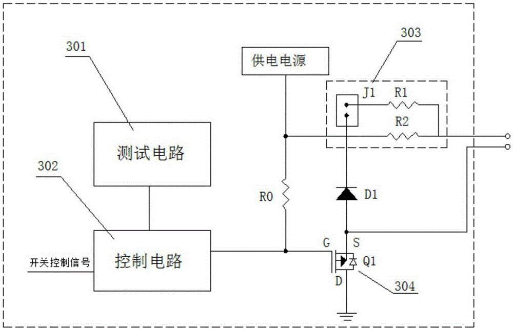
[0027] figure 2 It is a structural schematic di...


PUM


Abstract

The invention discloses a novel bus relay. The novel bus relay comprises a power supply, a single chip microcomputer control system, a driving system, a detecting system, a load, a bus interface and a bus; and the driving system further comprises a test circuit, a control circuit and a shift switch. Compared with the prior art, the novel bus relay has the beneficial effects that control circuit can only drive the relay to pull in when the voltage output by an AC/DC rectifying module reaches a set value, so that the main contact jitter of the relay is reduced, and the effective pulling in of the main contact of the relay is ensured; meanwhile, the relay is mounted by the bus, so that the usage amount of cables in a power distributing system is reduced; the distributed installation, the debugging and the maintenance of the relay can be realized conveniently; and in addition, the driving system avoids the generation of arc and unstable output voltage when the relay is switched, so that the novel bus relay is quite wide in the application prospects.

Description

technical field [0001] The invention relates to a relay, in particular to a novel bus relay, and belongs to the technical field of low-voltage switchgear and control equipment. Background technique [0002] Relay (English name: relay) is an electrical control device, which is an electrical appliance that causes the controlled quantity to undergo a predetermined step change in the electrical output circuit when the change of the input quantity (excitation quantity) meets the specified requirements. It has an interactive relationship between the control system (also known as the input loop) and the controlled system (also known as the output loop). Usually used in automatic control circuits, it is actually an "automatic switch" that uses small currents to control large current operations, so it plays the role of automatic adjustment, safety protection, and conversion circuits in the circuit. [0003] Relay is an automatic switching element with isolation function. It is widel...

Claims


Application Information

Patent Timeline
Patent Type & Authority Applications(China)
IPC IPC(8): H01H47/02
CPCH01H47/02
Inventor 林德松李培晋娜
Owner 成都霍睦斯电气有限公司
Why Eureka
Try Eureka