
Evaporative cold air source heat pump unit

An air source heat pump and source heat pump technology, applied in heat pumps, refrigerators, refrigeration components, etc., can solve problems such as unfavorable evaporative cold air source heat pump unit work, take away, and easy generation of frost mist at the intake end.

Inactive Publication Date: 2021-05-07
杭州美奇餐饮服务有限公司
View PDF0 Cites 0 Cited by
  • Summary
  • Abstract
  • Description
  • Claims
  • Application Information

AI Technical Summary

Problems solved by technology

[0004] The purpose of the present invention is to provide an evaporative cold air source heat pump unit to solve the problem of frost fog at the air intake end when the evaporative cold air source heat pump unit in the prior art works in a low temperature environment. This phenomenon is not conducive to the work of the evaporative cold air source heat pump unit, and some heat generated by the evaporative cold air source heat pump unit during work will be taken away by the heat sink, which cannot be recycled, resulting in a waste of resources

Method used


Image

  • Evaporative cold air source heat pump unit
  • Evaporative cold air source heat pump unit
  • Evaporative cold air source heat pump unit

Examples


Embodiment Construction

[0026] The following will clearly and completely describe the technical solutions in the embodiments of the present invention with reference to the accompanying drawings in the embodiments of the present invention. Obviously, the described embodiments are only some, not all, embodiments of the present invention. The specific embodiments described here are only used to explain the present invention, not to limit the present invention. Based on the embodiments of the present invention, all other embodiments obtained by persons of ordinary skill in the art without making creative efforts belong to the protection scope of the present invention.

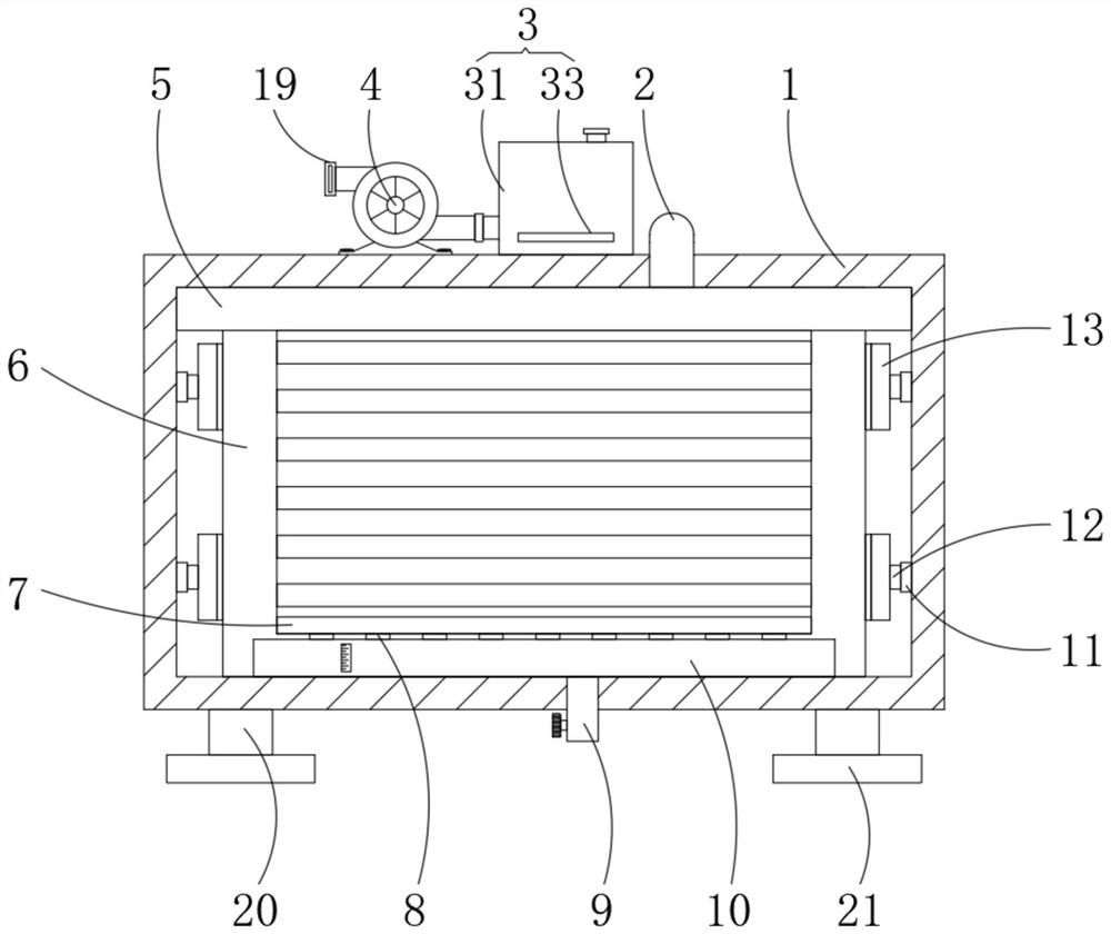
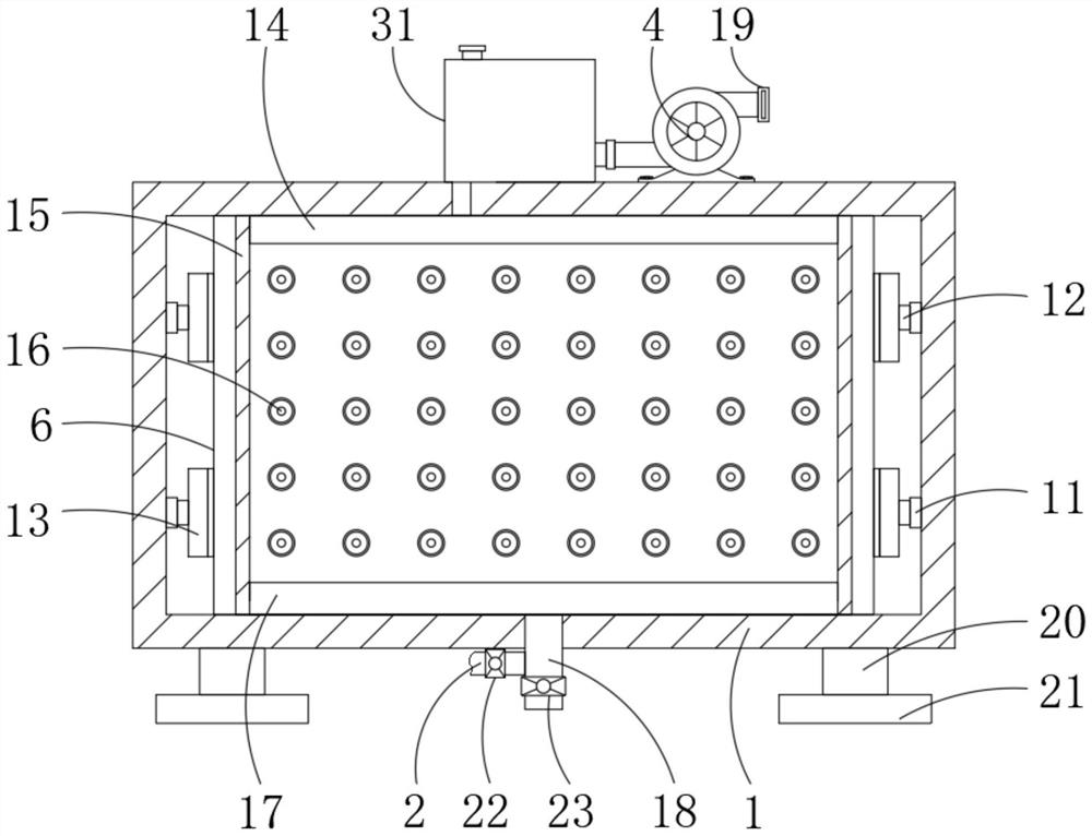
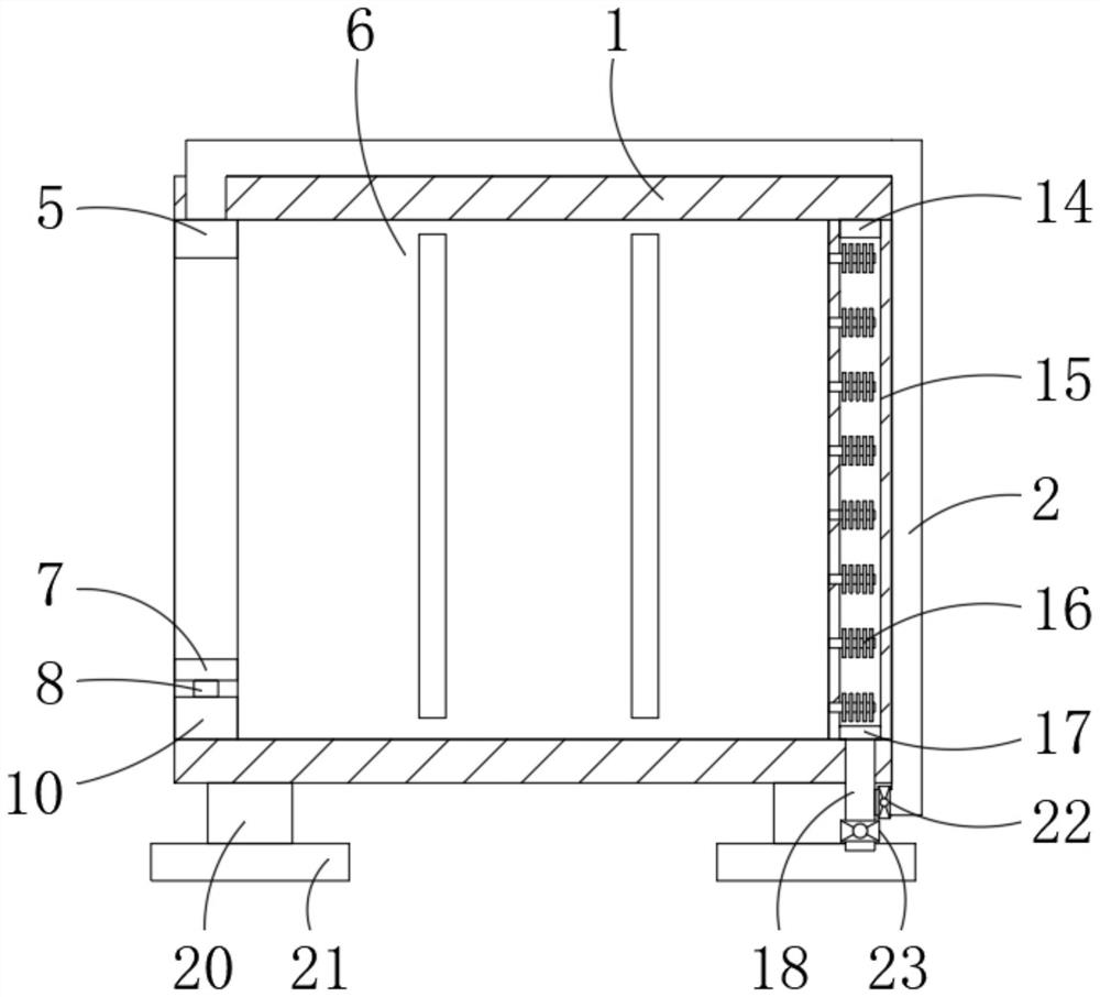
[0027] The present invention provides such Figure 1-5 The shown evaporative cold air source heat pump unit includes a housing 1, the inner cavity of the housing 1 is fixedly installed with an air source heat pump unit body 6, and one side of the top of the housing 1 is fixedly installed with an air pump 4, and the inlet of the air pump 4...


PUM


Abstract

The invention discloses an evaporative cold air source heat pump unit which comprises a shell. An air source heat pump unit body is fixedly installed in an inner cavity of the shell, an air pump is fixedly installed on one side of the top of the shell, and a refrigeration mechanism is fixedly installed at the air outlet end of the air pump. Through the arrangement of the air pump, when the air pump works, the air outlet end of the air pump conveys air to an inner cavity of a second air dispersion plate through the refrigeration mechanism, heat dissipation fins absorb heat generated by working of the air source heat pump unit body, the second air dispersion plate blows the heat dissipation fins, and then heat on the surfaces of the heat dissipation fins is taken away. The air with heat enters an inner cavity of an air collection plate and then is conveyed to an inner cavity of an air conveying pipe through an exhaust pipe, the air conveying pipe conveys the hot air to an inner cavity of a first air dispersion plate, the first air dispersion plate enables the hot air to blow the air inlet part on the front face of the air source heat pump unit body, and then frost at the air inlet part of the air source heat pump unit body is removed.

Description

technical field [0001] The invention belongs to the technical field of air source heat pump unit equipment, in particular to an evaporative cold air source heat pump unit. Background technique [0002] The air source heat pump unit is composed of four main components: evaporator, condenser, compressor and expansion valve, which constitute a closed system, which is filled with an appropriate amount of working fluid. The evaporator absorbs the heat in the air and evaporates to form steam (vaporization). The latent heat of vaporization is the recovered heat, which is then compressed into a high-temperature and high-pressure gas by the compressor, and condensed into a liquid state (liquefaction) in the condenser to send the absorbed heat to In the water to be heated, the liquid working medium returns to the expansion valve after being decompressed and expanded by the expansion valve, absorbing heat and evaporating to complete a cycle, and so on, continuously absorbing the heat o...

Claims


Application Information

Patent Timeline
IPC IPC(8): F25B30/06F25B47/00F25B43/00F25B41/20
CPCF25B30/06F25B43/003F25B47/00
Inventor 欧阳文生
Owner 杭州美奇餐饮服务有限公司
Learn More