Withstand voltage test fixture for stator connector with thermistor and test method thereof
A technology of withstand voltage test and thermistor, which is used in testing dielectric strength, thermometer testing/calibration, components of electrical measuring instruments, etc. , to achieve the effect of ensuring accuracy
- Summary
- Abstract
- Description
- Claims
- Application Information
AI Technical Summary
Problems solved by technology
Method used
Image
Examples
Embodiment 1
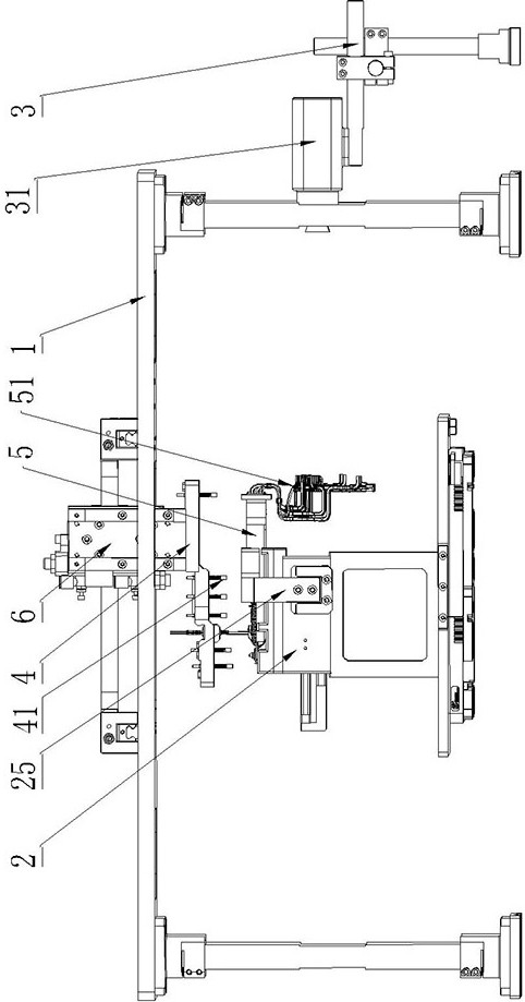
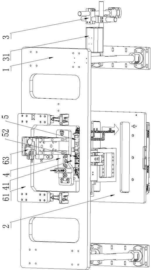
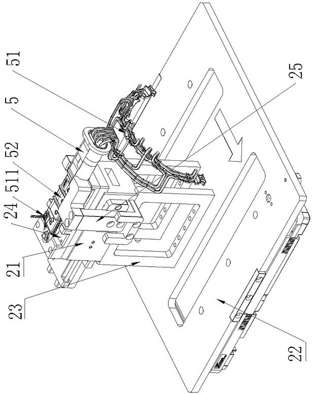
[0034] like Figure 1-6As shown, this embodiment relates to a stator connector withstand voltage test fixture with a thermistor, including a fixing frame 1; The fixed seat 2 fixes the stator connector 5 horizontally; the infrared thermal imager 3, the infrared thermal imager 3 is placed under the fixed frame 1, and the infrared thermal imager 3 is provided with a thermistor 51 surface temperature for detecting the stator connector 5 The detection head 31; the PIN needle connector 4, the PIN needle connector 4 is movably connected to the stator connector fixing seat 2 through a pressing device 6, and the PIN needle connector 4 is provided with multiple PIN needles 41, and multiple PIN needles 41 The pin 41 is crimped with the corresponding conductive terminal 52 on the stator connector 5 .
[0035] By adding a thermistor 51 to detect the temperature next to the motor after the actual stator connector 5 is installed, it is judged whether the motor is working abnormally, so as t...
Embodiment 2
[0048] A test method for a stator connector withstand voltage test fixture with a thermistor, comprising the following steps:
[0049] S1. Insert the toggle block 255 into the through hole 2541, push the toggle block 255 to drive the support rod 2542 to move horizontally, the support rod 2542 drives the slider 254 to move, and the slider 254 drives the buckle block 251 through the first connecting plate 252 Move away from the receiving block 24 side.
[0050] At this time, it is equivalent to opening the entire snap-fit limiting structure, which is convenient for the stator connector 5 to be put in.
[0051] S2. Drive the pressing device 6 to lift the PIN needle connector 4 .
[0052] In this step, specifically: drive the first air cylinder 62 to lift the support plate 61 , and then lift the PIN pin connector 4 . The movement of the buckle block 251 is to free up space in the horizontal direction, and then lift the PIN pin connector 4 to free up space in the vertical direc...
PUM
 Abstract
Description
Claims
Application Information
 - R&D
- Intellectual Property
- Life Sciences
- Materials
- Tech Scout
- Unparalleled Data Quality
- Higher Quality Content
- 60% Fewer Hallucinations
Browse by: Latest US Patents, China's latest patents, Technical Efficacy Thesaurus, Application Domain, Technology Topic, Popular Technical Reports.
© 2025 PatSnap. All rights reserved.Legal|Privacy policy|Modern Slavery Act Transparency Statement|Sitemap|About US| Contact US: help@patsnap.com


