Check patentability & draft patents in minutes with Patsnap Eureka AI!

Rapid imaging method for sparse array sparse frequency point plane scanning system

A technology of sparse frequency point and sparse array, applied in the field of rapid imaging of sparse array sparse frequency point planar scanning system, can solve the problems of high computing resource requirements and low computing efficiency, and achieve the goal of saving scanning time, saving cost, and reducing time Effect

Pending Publication Date: 2021-05-07
博微太赫兹信息科技有限公司
View PDF0 Cites 2 Cited by
  • Summary
  • Abstract
  • Description
  • Claims
  • Application Information

AI Technical Summary

Problems solved by technology

[0004] The technical problem to be solved by the present invention is: how to solve the problems of high computing resource requirements and low computing efficiency in the existing imaging methods, and provides a sparse array sparse frequency point planar scanning system rapid imaging method, by obtaining the target The distance distribution function only needs to reconstruct the two-dimensional image of the target. Compared with the traditional three-dimensional reconstruction algorithm, the calculation process is simpler and the calculation efficiency is higher. It adopts a one-dimensional sparse array configuration, and the receiving array element is compared with the dense array receiving The number of array elements is the same, but the transmitting array elements are sparse, so the total number of array elements can be greatly reduced, and the corresponding hardware cost can also be reduced. At the same time, the sparse signal system is adopted in the signal mode, so that the scanning of the array dimension increased speed

Method used


Image

  • Rapid imaging method for sparse array sparse frequency point plane scanning system
  • Rapid imaging method for sparse array sparse frequency point plane scanning system
  • Rapid imaging method for sparse array sparse frequency point plane scanning system

Examples


Embodiment Construction

[0028] The embodiments of the present invention are described in detail below. This embodiment is implemented on the premise of the technical solution of the present invention, and detailed implementation methods and specific operating procedures are provided, but the protection scope of the present invention is not limited to the following implementation example.

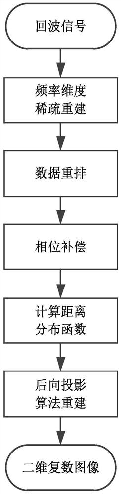
[0029] Such as figure 1 As shown, this embodiment provides a technical solution: a sparse array sparse frequency point planar scanning system rapid imaging method, including the following specific process:

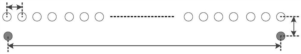
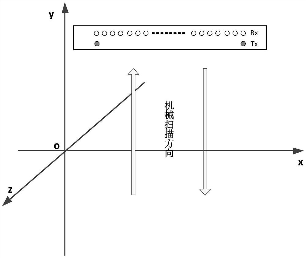
[0030] The millimeter-wave one-dimensional sparse array configuration is as follows figure 2 As shown, the gray solid array element is the transmitting array element, and the white hollow array element is the receiving array element. The spatial coverage of the horizontal dimension of the one-dimensional sparse array is 0.99m, and the distance between the transmitting array elements is Δx T =0.99m, the dista...


PUM


Abstract

The invention discloses a rapid imaging method for a sparse array sparse frequency point plane scanning system, and belongs to the millimeter wave personal safety inspection application technology field. The method comprises the following steps: S1, collecting echo signals; S2, carrying out frequency dimension sparse reconstruction; S3, rearranging the data; S4, performing phase compensation; S5, calculating a distance distribution function; and S6, reconstructing by a back projection algorithm. The target distance distribution function is obtained, only the two-dimensional image of the target needs to be reconstructed, and compared with a traditional three-dimensional reconstruction algorithm, the calculation process is simple, and the calculation efficiency is high; and a one-dimensional sparse array configuration is adopted, the number of the receiving array elements is consistent with that of the receiving array elements of a dense array, but the transmitting array elements are sparse, so that the total number of the array elements can be greatly reduced, and the corresponding hardware cost can also be reduced. And meanwhile, a sparse signal system is adopted in a signal mode, so that the scanning speed of the array dimension is improved.

Description

technical field [0001] The invention relates to the technical field of small passenger flow and high-precision millimeter-wave personal safety inspection applications, and in particular to a rapid imaging method of a sparse array sparse frequency point plane scanning system. Background technique [0002] Millimeter-wave array holographic imaging technology has been widely used in the field of personal security inspection. In recent years, the millimeter-wave array plane scanning holographic imaging system has been applied to millimeter-wave human body security inspection devices, and some manufacturers have realized commercial applications, truly realizing millimeter-wave Industrialization of technology. [0003] At present, the human body security detector of the planar scanning system uses a one-dimensional dense array. The traditional one-dimensional millimeter-wave dense array holographic imaging algorithm uses the classic back-projection algorithm, wave number domain al...

Claims


Application Information

Patent Timeline
IPC IPC(8): G01V8/10G01V8/00
CPCG01V8/10G01V8/005
Inventor 孟祥新高炳西李霆安德越
Owner 博微太赫兹信息科技有限公司
Features
  • R&D
  • Intellectual Property
  • Life Sciences
  • Materials
  • Tech Scout
  • Unparalleled Data Quality
  • Higher Quality Content
  • 60% Fewer Hallucinations
Learn More