Liquid crystal screen heat dissipation structure of projection ray machine

A heat-dissipating structure and technology for a projector, applied in the field of projectors, can solve problems such as the decline of the optical performance of the optical components of the projector and the reduction of the service life of the projector, and achieve the effect of improving the service life and improving the heat dissipation efficiency.

Pending Publication Date: 2021-05-07
深圳瑞视达科技有限公司
View PDF0 Cites 3 Cited by
  • Summary
  • Abstract
  • Description
  • Claims
  • Application Information

AI Technical Summary

Problems solved by technology

The projector optics work at high temperature for a long time, which will reduce the optical performance of the projector optics, which will greatly reduce the service life of the projector

Method used


Image

  • Liquid crystal screen heat dissipation structure of projection ray machine
  • Liquid crystal screen heat dissipation structure of projection ray machine
  • Liquid crystal screen heat dissipation structure of projection ray machine

Examples


Embodiment 1

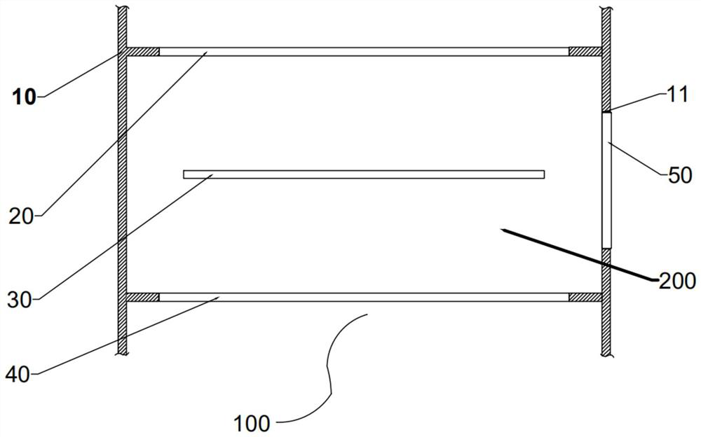
[0024] Such as figure 1 As shown, the embodiment of the present invention provides a heat dissipation structure 100 for a projection optical machine liquid crystal screen, which includes a casing 10, in which a first lens 20, a liquid crystal screen 30, and a second lens 40 are sequentially arranged along the optical path. The space between the first lens 20 and the second lens 40 forms a sealed cavity 200 through the casing 10, and an opening 11 is provided on the wall of the casing 10 in the cavity 200, and a semiconductive cooling chip 50 is arranged at the opening 11 and the The opening 11 is sealed, the cooling surface of the semiconductor cooling chip 50 faces into the cavity 200 , and the heating surface of the semiconductor cooling chip 50 faces outside the casing 10 .

[0025] In the embodiment of the present invention, by accommodating the liquid crystal screen 30 in the cavity 200 which is sealed by the first lens 20, the second lens 40 and the casing 10, an opening...

Embodiment 2

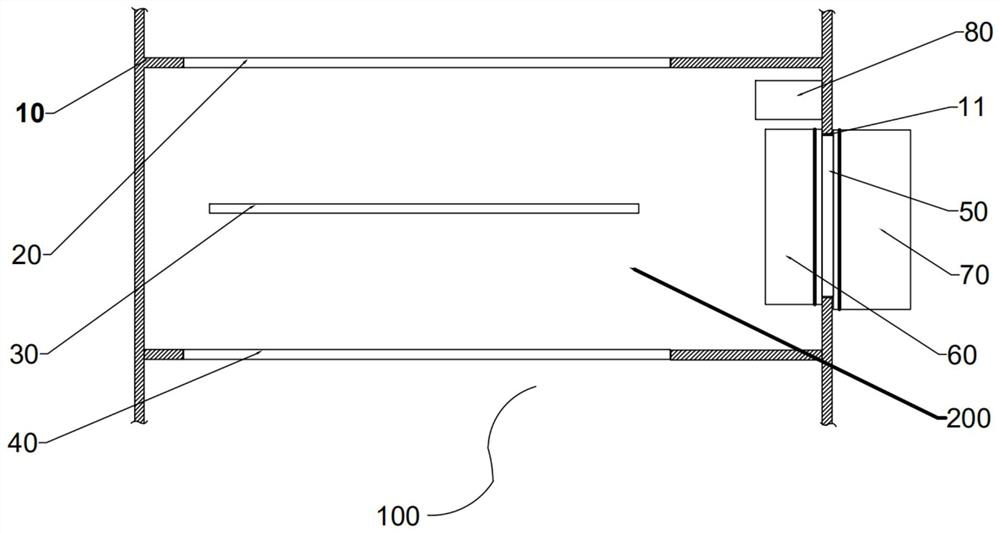
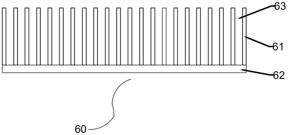
[0027] Such as figure 2 and image 3 As shown, the embodiment of the present invention proposes a new technical solution based on the first embodiment to further improve the cooling efficiency of the cavity in the sealed cavity. The embodiment of the present invention also includes an internal A radiator 60 , the inner radiator 60 is attached to the cooling surface of the semiconductor cooling sheet 50 . In the embodiment of the present invention, by increasing the inner radiator 60, the contact area between the cooling surface and the air in the sealed cavity 200 is increased, thereby improving the cooling efficiency.

[0028] In the embodiment of the present invention, the preferred structure of the inner radiator 60 includes a plurality of heat sinks 61 and a heat dissipation base 62. One end of the plurality of heat sinks 61 is mounted side by side on the heat dissipation base 62, and a heat dissipation structure is formed between the plurality of heat sinks 61. channel...

Embodiment 3

[0032] Such as Figure 4 As shown, the implementation of the present invention is a further improvement to Embodiment 2. A first ventilation channel 201 is formed between the liquid crystal screen 30 and the first lens 20, and a ventilation channel 201 is formed between the liquid crystal screen 30 and the second lens 40. A second ventilation channel 202 is formed, the first ventilation channel 201 and the second ventilation channel 202 form a circulation air path through the third ventilation channel 203 and the fourth ventilation channel 204, and the heat dissipation channel 63 of the inner radiator 60 and the circulating air The fan 80 is installed on the fourth ventilation passage 204 and circulates the air along the circulation air passage.

[0033] In the embodiment of the present invention, cooling air is circulated around the liquid crystal screen 30 to dissipate heat from the liquid crystal screen 30 .

[0034] In the embodiment of the present invention, in order to ...


PUM


Abstract

The invention relates to the technical field of projectors, and discloses a liquid crystal screen heat dissipation structure of a projection ray machine. The heat dissipation structure comprises a machine shell, a first lens, a liquid crystal screen and a second lens are sequentially arranged in the machine shell along a light path channel, a sealed cavity is formed in the space between the first lens and the second lens through the machine shell, and an opening is formed in the wall of the machine shell in the cavity. A semiconductor chilling plate is arranged at the opening and seals the opening, the refrigerating face of the semiconductor chilling plate faces the interior of the cavity, and the heating face of the semiconductor chilling plate faces the exterior of the machine shell. According to the projection light machine liquid crystal screen heat dissipation structure, the liquid crystal screen is contained in the sealed cavity, air in the cavity is refrigerated, and therefore heat dissipation of the liquid crystal screen is achieved, the heat dissipation efficiency of the liquid crystal screen is improved on the premise that the projection effect is guaranteed, and the service life of a projector is prolonged.

Description

technical field [0001] The invention relates to the technical field of projectors, in particular to a heat dissipation structure of a liquid crystal screen of a projection light machine. Background technique [0002] Projector, which uses a full-color TFT LCD screen as the light valve, with the help of a certain designed Kohler lighting system, is composed of light source, condenser mirror, front Fresnel lens, LCD screen, rear Fresnel lens and lens, etc. imaging projector. However, since the transmittance of the LCD screen is only 6-10%, its efficiency is only 6-10%, and the remaining 90-94% of the light is all concentrated on the LCD screen and absorbed by the LCD screen, which is reflected in the form of heat. The temperature of the LCD screen is very high, and the high temperature of the LCD screen will spread inside the projector, increasing the internal temperature of the projector. The projector optics work at high temperature for a long time, which will reduce the o...

Claims


Application Information

Patent Timeline
Patent Type & Authority Applications(China)
IPC IPC(8): G03B21/16G03B21/00
CPCG03B21/006G03B21/16
Inventor 刘清卫
Owner 深圳瑞视达科技有限公司
Why Eureka
Try Eureka