A Boundary Setting Method for Turbulent Kinetic Energy Entrance of Flow Around a Hypersonic Blunt Front

A hypersonic, turbulent kinetic energy technology, applied in design optimization/simulation, computer-aided design, instruments, etc., can solve the problems of underestimating turbulent kinetic energy, inaccurate reflection, and large differences in calculation results, achieving high achievability, Reasonable and highly reliable results

Active Publication Date: 2021-06-29
CALCULATION AERODYNAMICS INST CHINA AERODYNAMICS RES & DEV CENT
View PDF5 Cites 0 Cited by
  • Summary
  • Abstract
  • Description
  • Claims
  • Application Information

AI Technical Summary

Problems solved by technology

It can be seen that the calculation results of the two methods are quite different. Compared with DNS, the RANS equation overestimates the turbulent kinetic energy in most of the flow field after the shock wave, and underestimates the turbulent kinetic energy in the boundary layer, which cannot correctly reflect The distribution of turbulent kinetic energy near the wall that affects boundary layer turbulence / transition calculations
Therefore, in the RANS numerical simulation of hypersonic turbulence / transition, the method of using the free-flow turbulence degree to set the incoming flow boundary condition is no longer applicable, and the free-flow turbulent kinetic energy after the shock wave cannot be correctly estimated, and a new inlet boundary setting technology is required

Method used


Image

  • A Boundary Setting Method for Turbulent Kinetic Energy Entrance of Flow Around a Hypersonic Blunt Front
  • A Boundary Setting Method for Turbulent Kinetic Energy Entrance of Flow Around a Hypersonic Blunt Front
  • A Boundary Setting Method for Turbulent Kinetic Energy Entrance of Flow Around a Hypersonic Blunt Front

Examples


Embodiment Construction

[0051] All features disclosed in all embodiments in this specification, or steps in all implicitly disclosed methods or processes, except for mutually exclusive features and / or steps, can be combined and / or extended and replaced in any way.

[0052] Such as Figure 1~10 As shown, a hypersonic blunt front flow around the turbulent kinetic energy inlet boundary setting method, including the following steps:

[0053] S1, calculate the basic flow field, and obtain the steady basic flow field variables ;

[0054] S2, use the numerical simulation system to directly simulate the disturbance wave to obtain unsteady flow field variables ϕ ;

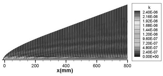
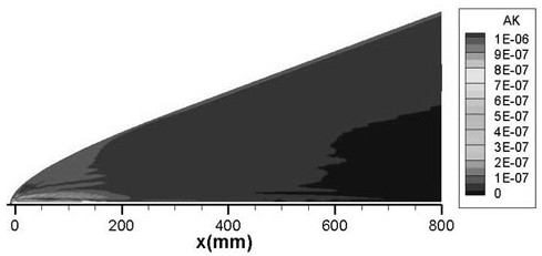
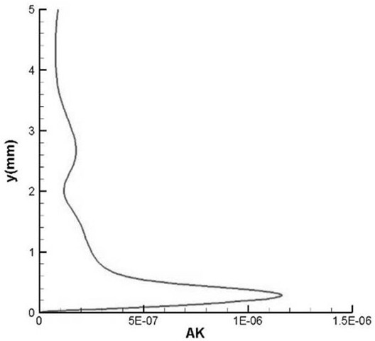
[0055] S3, analyze the flow field to get the disturbance field ϕ' , and obtain the turbulent kinetic energy distribution characteristics;

[0056] S4, set the turbulent kinetic energy inlet boundary;

[0057] S5, calculate turbulence / transition.

[0058] Further, in step S1, the calculation domain is established, the boundary conditions ...


PUM


Abstract

The invention discloses a method for setting the turbulent kinetic energy inlet boundary of a hypersonic obtuse leading edge flow, which includes the following steps: S1, calculating the basic flow field, and obtaining the steady basic flow field variable; S2, using a numerical simulation system to directly simulate the disturbance wave, Get unsteady flow field variables ϕ ; S3, analyze the flow field to get the disturbance field ϕ' , and obtain the distribution characteristics of the turbulent kinetic energy; S4, set the inlet boundary of the turbulent kinetic energy; S5, calculate the turbulent flow / transition, etc.; the present invention does not need to modify the turbulent kinetic energy equation in the turbulent flow model, and the turbulent kinetic energy can be avoided by setting the inlet boundary condition The calculation deviation of the equation in the downstream of the shock wave is based on the direct numerical simulation results to set a more accurate turbulent kinetic energy inlet boundary condition, which has the advantages of reasonable calculation results, high achievability, and high reliability, and can be extended to three-dimensional flow conditions, etc.

Description

technical field [0001] The invention relates to the field of initial disturbance amplitude estimation in a boundary layer in a blunt front hypersonic flow, and more specifically, relates to a method for setting a boundary of a turbulent kinetic energy inlet of a hypersonic blunt front flow. Background technique [0002] Turbulence / transition is a physical phenomenon that exists widely in nature, and it has important scientific research significance and engineering application value in the field of aviation / astronautics. In the process of aircraft development, it is necessary to accurately calculate the location and range of boundary layer turbulence / transition, because compared with laminar flow, turbulence / transition will have a greater impact on the boundary layer, mainly showing wall friction and heat flow. They affect the aerodynamic properties of the aircraft, such as lift-to-drag ratio, range, stability, handling characteristics, as well as thermal protection and paylo...

Claims


Application Information

Patent Timeline
Patent Type & Authority Patents(China)
IPC IPC(8): G06F30/15G06F30/28G06F119/10G06F119/14
CPCG06F30/15G06F30/28G06F2119/10G06F2119/14Y02T90/00
Inventor 张毅锋向星皓陈坚强袁先旭陈曦
Owner CALCULATION AERODYNAMICS INST CHINA AERODYNAMICS RES & DEV CENT
Why Eureka
Try Eureka