A layered gradient porous material sweat cooling structure and aircraft

A porous material, sweat cooling technology, applied in the direction of instrumentation, geometric CAD, design optimization/simulation, etc., can solve the problems of uneven heat dissipation, high cost, poor thermal protection effect, etc., achieve low cost, stable control, overcome partial The effect of the hot spot effect

Active Publication Date: 2021-06-29
CALCULATION AERODYNAMICS INST CHINA AERODYNAMICS RES & DEV CENT
View PDF11 Cites 1 Cited by
  • Summary
  • Abstract
  • Description
  • Claims
  • Application Information

AI Technical Summary

Problems solved by technology

[0006] In order to overcome the deficiencies of the prior art, the present invention provides a layered gradient porous material sweating cooling structure and an aircraft to solve the deficiencies of the prior art such as uneven heat dissipation, poor thermal protection effect, and high cost

Method used


Image

  • A layered gradient porous material sweat cooling structure and aircraft
  • A layered gradient porous material sweat cooling structure and aircraft
  • A layered gradient porous material sweat cooling structure and aircraft

Examples


Embodiment 1

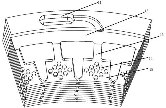
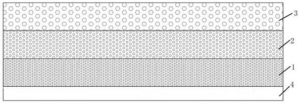
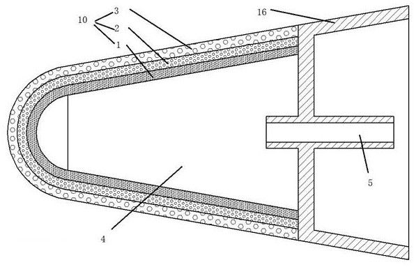
[0041] Such as Figure 1 to Figure 3 As shown, a layered gradient porous material sweat cooling structure includes N layers of porous material layers 10, a cooling cavity 4 arranged on one side of the porous material layer 10, and a coolant supply unit 5 is arranged in the cooling cavity 4, so The coolant supply unit 5 is used to supply the coolant to the cooling cavity 4, and the porosity of the porous material layer 10 decreases layer by layer along the direction close to the cooling cavity 4, wherein N is an integer, and N≥2.

[0042] The present invention draws lessons from the high-friction characteristics of the lamination cooling structure control channel and the low-friction characteristics of the diffuse flow channel. The N-layer porous material layer 10 adopts porous material, and the porosity of the porous material layer 10 is sequentially pressed along the direction close to the cooling chamber 4. The layers are reduced, the porosity of the layer of porous material...

Embodiment 2

[0050] Such as Figure 1 to Figure 3 As shown, as a further optimization of Embodiment 1, this embodiment includes all the technical features of Embodiment 1. In addition, this embodiment also includes the following technical features:

[0051] As a preferred technical solution, the coolant supplied by the coolant supply unit 5 is a gaseous or liquid substance.

[0052] The gaseous or liquid coolant has good flow performance, which is conducive to the adequacy of heat exchange, further enhances the uniformity of heat exchange and temperature stability, and is convenient for storage.

[0053] As a preferred technical solution, the material of the N-layer porous material layer 10 is ceramic or stainless steel.

[0054] Ceramic or stainless steel has a high melting point, and it is easy to choose to make a porous material structure, which is convenient for procurement and maintenance.

[0055] As a preferred technical solution, the porosity of the N-layer porous material layer ...

Embodiment 3

[0061] Such as Figure 1 to Figure 3 As shown, this embodiment provides an aircraft, including the above-mentioned layered gradient porous material sweating cooling structure.

[0062] The layered gradient porous material sweating cooling structure of the aircraft draws lessons from the high frictional resistance characteristics of the laminated sweating cooling structure control channel and the low frictional resistance characteristic of the diffuse flow channel. The N-layer porous material layer 10 adopts porous material, and the porosity of the porous material layer 10 is along The direction close to the cooling chamber 4 decreases successively according to the layers. The layer of the porous material layer 10 close to the cooling chamber 4 has a small porosity and a large proportion of flow resistance, which is similar to the control channel of the laminate sweating cooling structure; the porous material layer 10 is far away from the cooling chamber. The layer porosity of ...


PUM

PropertyMeasurementUnit
porosityaaaaaaaaaa
porosityaaaaaaaaaa

Abstract

The invention discloses a layered gradient porous material sweating cooling structure and an aircraft. The sweating cooling structure comprises N layers of porous material layers and a cooling cavity arranged on one side of the porous material layer. A coolant supply unit is arranged in the cooling cavity , the coolant supply unit is used to supply coolant to the cooling cavity, the porosity of the porous material layer decreases layer by layer along the direction close to the cooling cavity, wherein, N is an integer, N≥2. The invention solves the problems of uneven heat dissipation, poor heat protection effect, high cost and the like existing in the sweating cooling structure in the prior art.

Description

technical field [0001] The invention relates to the technical field of aircraft thermal protection, in particular to a layered gradient porous material sweating cooling structure and an aircraft. Background technique [0002] With the further acceleration of hypersonic vehicles, higher requirements are put forward for thermal protection. The nose cone, rudder leading edge, inlet lip, engine wall, and tail nozzle of hypersonic vehicles will all be impacted by high-temperature thermal airflow. Therefore, the development of an efficient and stable active thermal protection system has become a key technology in this field. The existing active thermal protection technologies mainly include convective cooling, air film cooling and sweat cooling. [0003] The traditional sweating cooling technology draws on the method of sweating and heat dissipation of living organisms. The cooling medium overflows from the dense pores of the porous material uniformly and slowly from the surface ...

Claims


Application Information

Patent Timeline
Patent Type & Authority Patents(China)
IPC IPC(8): G06F30/28G06F30/15
CPCG06F30/15G06F30/28G06F2113/08G06F2119/08G06F2119/14
Inventor 沈斌贤李强刘骁葛强周述光
Owner CALCULATION AERODYNAMICS INST CHINA AERODYNAMICS RES & DEV CENT
Why Eureka
Try Eureka