Gradient Multi-Order Rectangular Close-Packed Quasi-Self-Complementary Antenna
A close-packed, rectangular technology, applied in the field of gradual multi-order rectangular close-packed frequency-expanding quasi-self-complementary antennas, can solve the problems of insufficient bandwidth, large energy loss in design technology, and difficult control, etc., to achieve large radiation gain and improve impedance matching characteristics, the effect of increasing the effective radiation area
- Summary
- Abstract
- Description
- Claims
- Application Information
AI Technical Summary
Problems solved by technology
Method used
Image
Examples
Embodiment 1
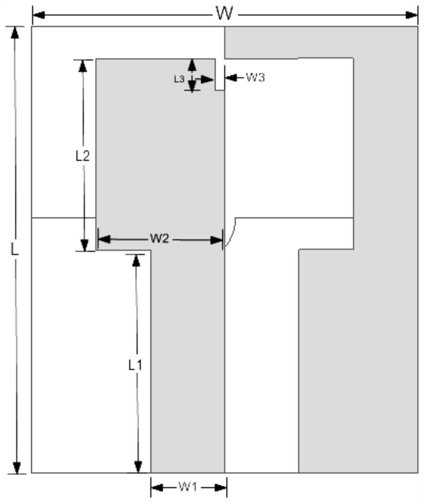
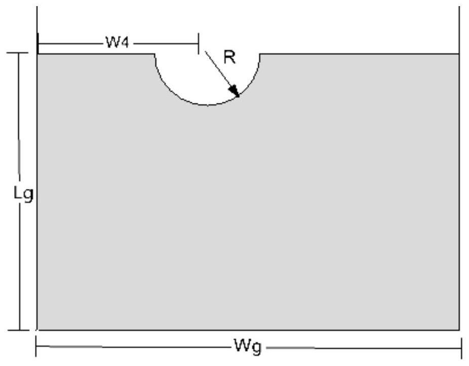
[0027] see figure 1 , the present embodiment takes n=1, that is, a first-order gradient rectangular close-packed frequency extension quasi-self-complementary antenna, and its left radiation patch is a rectangle, with a length of L2=5.6mm and a width of W2=3.8mm; the rectangular radiation patch There is a rectangular gap in the upper right corner of the chip, the length of which is L3=1.1mm, and the width is W3=0.3mm; a 50-ohm impedance matching input microstrip feeder is used, and the length is L1=7.5mm, and the width is W1=2.3mm; figure 2 It is the rear view of the first-order embodiment, the height of the lower end of the metal ground plate is Lg=8mm, and the width is equivalent to the outer contour width of the low-power high-performance dielectric double-sided copper-clad substrate, which is Wg=W=12mm, on the top of the metal ground plate There is a semicircular groove for controlling impedance matching, the horizontal distance between the center of the circle and the lef...
Embodiment 2
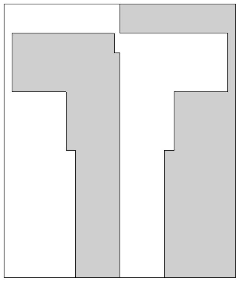
[0029] see image 3 , the present embodiment takes n=2, that is, the second-order gradient rectangular close-packed frequency expansion quasi-self-complementary antenna, the rectangular basic unit with the scale control ratio of each layer takes the same size, its length is L2=3.1mm, and its width is W2=2.75 mm; the length of the gap in the upper right corner of the left radiation patch is L3=1mm, and the width is W3=0.3mm; a 50-ohm impedance matching input microstrip feeder is used, and its length is L1=6.5mm, and its width is W1=2.3mm; metal connection The shape of the floor is the same as that of the first-order embodiment. The height of the lower end of the metal ground plate is Lg=7.8mm, and the width is equivalent to the width of the outer contour of the low-power and high-performance dielectric double-sided copper-clad substrate, which is Wg=W=12mm. There is a semicircular groove on the top of the grounding plate to control impedance matching. The horizontal distance be...
Embodiment 3
[0031] see Figure 4 , the present embodiment takes n=3, that is, the third-order gradient rectangular close-packed frequency-expanding quasi-self-complementary antenna, the rectangular basic unit with the scale control ratio of each layer takes the same size, its length is L2=2.5mm, and its width is W2=1.85 mm; the length of the gap in the upper right corner of the left radiation patch is L3=0.8mm, and the width is 0.2mm; a 50-ohm gradual impedance matching input microstrip feeder is adopted, and its length is L1=5.3mm, and the width is gradually changed to W1=2.3mm 1.5mm; the shape of the metal ground plate is the same as that of the first-order embodiment, the height of the lower end of the metal ground plate is Lg=6.2mm, and the width is equivalent to the outer contour scale width of the low-power high-performance dielectric double-sided copper-clad substrate, which is Wg=W= 12mm, on the top of the metal grounding plate, there is a semicircular groove for controlling imped...
PUM
 Abstract
Description
Claims
Application Information
 - R&D
- Intellectual Property
- Life Sciences
- Materials
- Tech Scout
- Unparalleled Data Quality
- Higher Quality Content
- 60% Fewer Hallucinations
Browse by: Latest US Patents, China's latest patents, Technical Efficacy Thesaurus, Application Domain, Technology Topic, Popular Technical Reports.
© 2025 PatSnap. All rights reserved.Legal|Privacy policy|Modern Slavery Act Transparency Statement|Sitemap|About US| Contact US: help@patsnap.com


