Bidirectional charging circuit, device and control method for power storage equipment
A technology for electric storage equipment and charging circuits, which is applied in the direction of battery circuit devices, circuit devices, load supply circuits, etc., can solve the problems of large overall circuit size, inability to charge synchronously, and large physical space, so as to reduce the scale of the circuit and save separate The space occupied and the effect of simplifying the circuit
Inactive Publication Date: 2021-05-07
GUANGZHOU ALLPOWERS IND INT
View PDF5 Cites 1 Cited by
- Summary
- Abstract
- Description
- Claims
- Application Information
AI Technical Summary
Problems solved by technology
However, the existing storage battery cannot be charged synchronously when it is discharged
In the existing technical solutions, the charging circuit and the discharging circuit are independent of each other, and the two independent modules occupy a large amount of physical space, which makes the bidirectional charging circuit with the charging module and the discharging module larger in scale, and the circuit is complicated
Method used
View moreImage
Smart ImageViewing Examples
Examples
 PUM
 Abstract
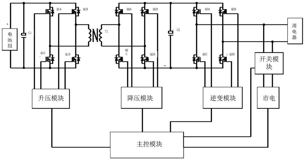
The invention discloses a bidirectional charging circuit for power storage equipment. The bidirectional charging circuit comprises a boost and buck switching module, an inversion and rectification module, a switch module and a main control module, wherein the boost and buckswitching module is provided with a battery connecting end connected with a battery pack, the switch module is provided with a load connecting end connected with an electric appliance and a first commercial power access end, and the main control module is provided with a second commercial power access end; the step-up and step-down switching module is connected with the inversion and rectification module, and the inversion and rectification module is connected with the switch module; and the main control module is respectively connected with the boost and buck switching module, the inversion and rectification module and the switch module. The invention provides a bidirectional charging circuit, device and control method for power storage equipment, and can provide a bidirectional charging solution for realizing charging and discharging.
Description
technical field [0001] The invention relates to the technical field of storage batteries, in particular to a bidirectional charging circuit, device and control method for storage equipment. Background technique [0002] The storage battery is charged by the charging module, and when the electric energy is output, the inverter module converts it into voltages of different specifications to supply power to the powered equipment. However, existing storage batteries cannot be simultaneously charged while being discharged. In the existing technical solutions, the charging circuit and the discharging circuit are independent of each other, and the two independent modules occupy a large amount of physical space, which makes the bidirectional charging circuit with the charging module and the discharging module larger in scale, and the circuit is complicated, and the circuit There are many components in the middle, which makes the volume of the whole circuit larger; in addition, the ...
Claims
Login to View More Application Information
Patent Timeline
 IPC IPC(8): H02J7/00H02J7/02H02J9/06
CPCH02J7/0068H02J7/02H02J7/0063H02J9/062H02J9/068H02J2207/20
Inventor 钟小军
Owner GUANGZHOU ALLPOWERS IND INT
Features
- R&D
- Intellectual Property
- Life Sciences
- Materials
- Tech Scout
- Unparalleled Data Quality
- Higher Quality Content
- 60% Fewer Hallucinations
Learn More Browse by: Latest US Patents, China's latest patents, Technical Efficacy Thesaurus, Application Domain, Technology Topic, Popular Technical Reports.
© 2025 PatSnap. All rights reserved.Legal|Privacy policy|Modern Slavery Act Transparency Statement|Sitemap|About US| Contact US: help@patsnap.com


