

Wide-field subcutaneous dilator
Patent Information
- Authority / Receiving Office
- CN · China
- Patent Type
- Applications(China)
- Current Assignee / Owner
- 陈春美
- Publication Date
- 2021-05-11
Smart Images
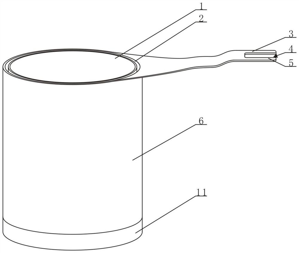
Figure 1 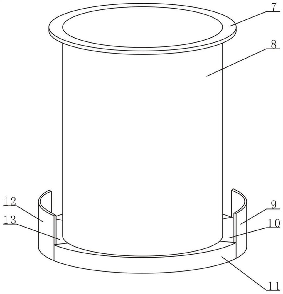
Figure 2 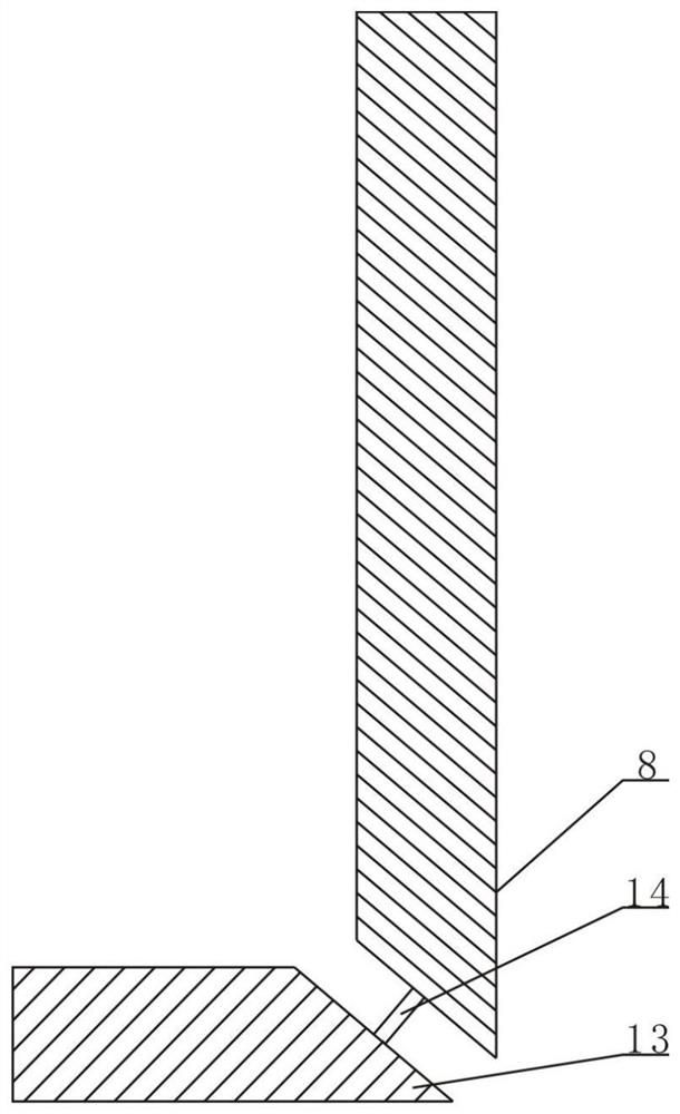
Figure 3
Abstract
Description
technical field
[0001] The invention relates to a wide-view subcutaneous dilator, which is applied in the field of medical surgery. Background technique
[0002] As is known, when performing minimally invasive operations such as spinal paravertebral or thoracic posterior paravertebral minimally invasive channel system treatment, it is necessary to incise a hole in the human body and expand the soft tissue at the incision so that surgical devices such as an endoscope can be removed from the body. The incision hole extends into the affected area. At present, most minimally invasive operations use multi-stage expansion sleeves to expand the tissue step by step. However, expanding the incision hole step by step leads to a longer reaming time, which in turn prolongs the minimally invasive surgery. time; and the existing expansion sleeve usually adopts a circular tubular structure, but usually only need to cut a long strip opening for the patient, and the long strip cutting hole i...