Eureka AIR delivers breakthrough ideas for toughest innovation challenges, trusted by R&D personnel around the world.

Electric power supply equipment with fire extinguishing function

A power supply and function technology, applied in substation/distribution device casing, electrical components, fire rescue, etc., can solve the problems of inconvenience, single function, loss, etc.

Active Publication Date: 2021-05-11
国网山东省电力公司高青县供电公司
View PDF6 Cites 0 Cited by
  • Summary
  • Abstract
  • Description
  • Claims
  • Application Information

AI Technical Summary

Problems solved by technology

[0004] However, the traditional distribution boxes currently on the market are relatively simple in functionality and very inconvenient to use. When a fire occurs during use of a traditional distribution box, it can only be extinguished by firefighters. The distribution box itself does not have automatic The function of fire extinguishing will cause the delay of the fire, which will easily cause greater losses

Method used


Image

  • Electric power supply equipment with fire extinguishing function
  • Electric power supply equipment with fire extinguishing function
  • Electric power supply equipment with fire extinguishing function

Examples


Embodiment 1

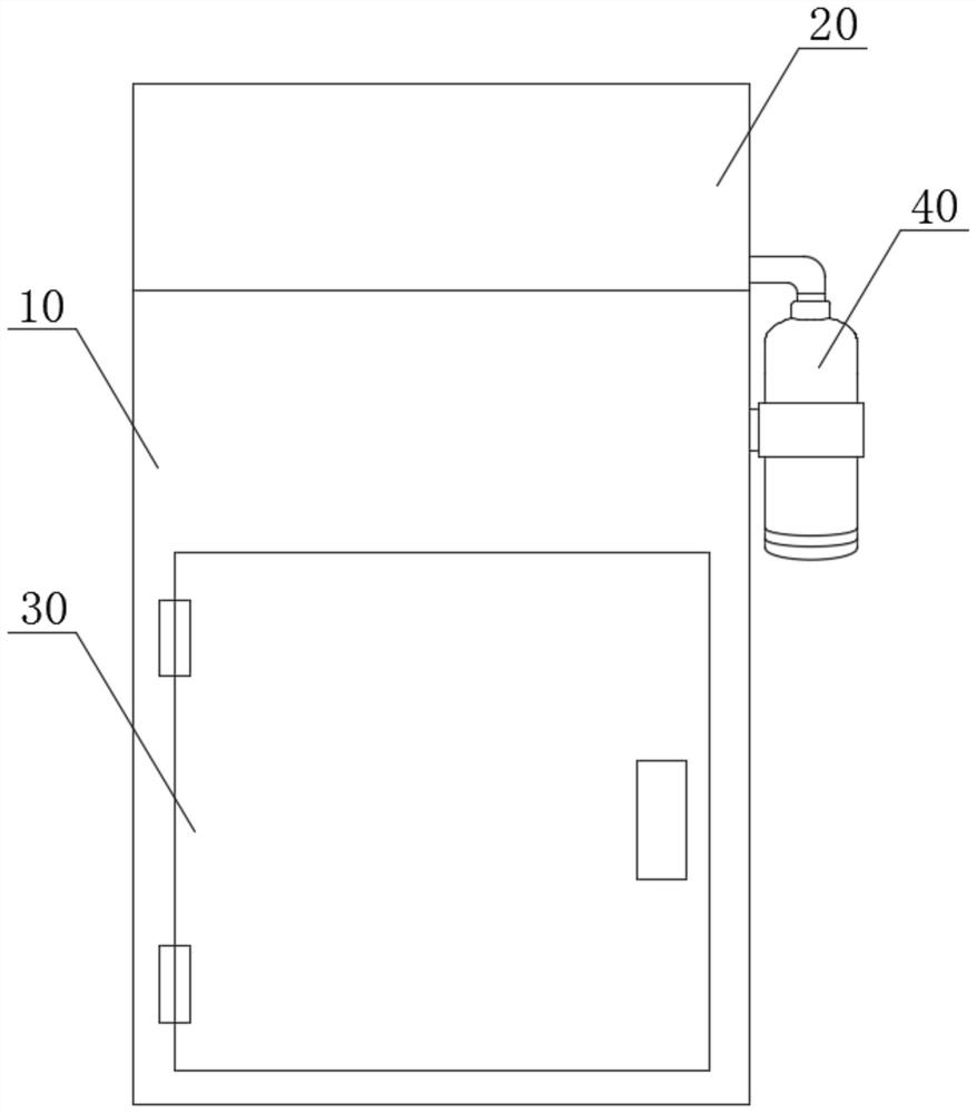
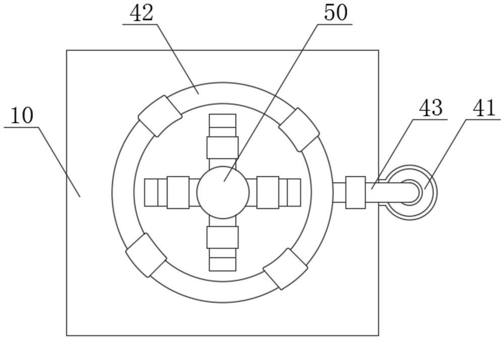
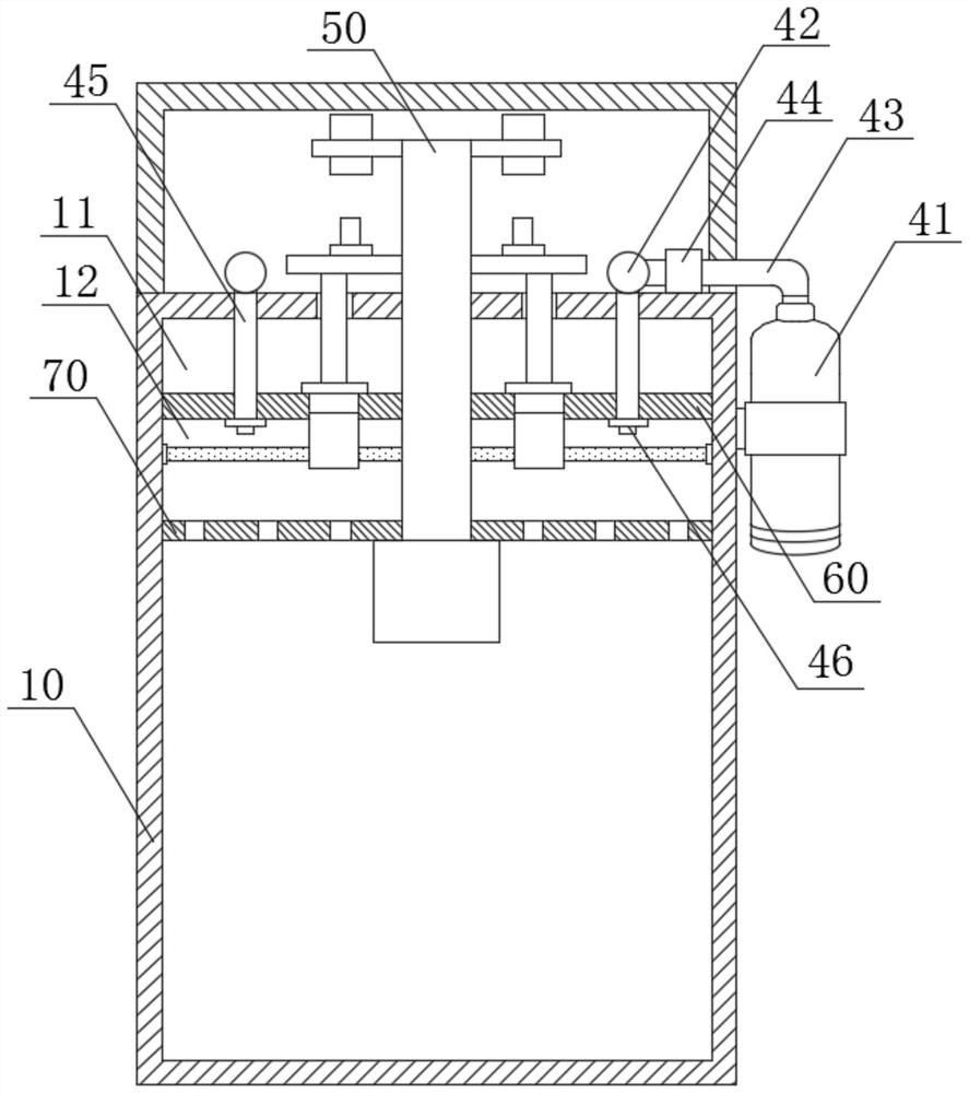
[0042] see Figure 1-6 , the present invention provides a technical solution: power supply equipment with fire extinguishing function, including: distribution box 10, fire extinguishing mechanism 40, reaction mechanism 50 and control mechanism 90.

[0043] Wherein, an upper partition 60 and a lower partition 70 are fixedly installed near the top inside the distribution box 10, and a storage chamber 11 is provided between the top of the upper partition 60 and the top inside the distribution box 10. The interior of the storage chamber 11 is filled with fire extinguishing materials 111, a mixing chamber 12 is provided between the bottom end of the upper partition 60 and the top end of the lower partition 70, and the bottom surface of the upper partition 60 is fixedly connected with a powder lowering pipe 61 .

[0044] Further, the mixing chamber 12 can realize the uniform mixing of the fire extinguishing material 111 and carbon dioxide, and then the carbon dioxide carries the fi...

Embodiment 2

[0079] see Figure 1-6 , the present invention provides a technical solution: power supply equipment with fire extinguishing function, fire extinguishing mechanism 40 and control mechanism 90 .

[0080] Wherein, the fire extinguishing mechanism 40 includes a carbon dioxide storage tank 41 and an air injection ring pipe 42, the outlet end of the carbon dioxide storage tank 41 is fixedly connected with a connecting conduit 43, and one end of the connecting conduit 43 is fixedly connected with the air injection ring pipe 42, so A solenoid valve 44 is fixedly installed inside the connecting conduit 43 , and an air injection branch pipe 45 is fixedly installed around the bottom end of the air injection ring pipe 42 .

[0081] Further, the contact switch 93 opens the solenoid valve 44, so that the connecting conduit 43 is opened, and the carbon dioxide in the carbon dioxide storage tank 41 will enter the gas injection ring pipe 42 through the connecting conduit 43, and then enter in...


PUM


Abstract

The invention discloses electric power supply equipment with a fire extinguishing function. The electric power supply equipment with the fire extinguishing function comprises a distribution box, an upper partition plate and a lower partition plate are fixedly installed at positions, close to the top end, in the interior of the distribution box, a storage cavity is formed between the top end of the upper partition plate and the top end in the interior of the distribution box, the interior of the storage cavity is filled with a fire extinguishing material, a mixing chamber is arranged between the bottom end of the upper partition plate and the top end of the lower partition plate, and powder feeding pipes are fixedly connected to the surface of the bottom end of the upper partition plate. According to the electric power supply equipment with the fire extinguishing function, through an installed reaction mechanism, carbon dioxide can carry the fire extinguishing material to penetrate through a through holes in the surface of the lower partition plate to uniformly flow into the distribution box, due to the fact that carbon dioxide is a non-combustible substance, the specific gravity of carbon dioxide is slightly heavier than that of air, the carbon dioxide can be attached to comburent after entering the distribution box, air is blocked, fire is extinguished; moreover, the fire extinguishing material can quickly cover the space in the distribution box, the fire extinguishing range is large, and therefore quick and effective fire extinguishing can be achieved, the spreading of fire disasters is avoided, and the use safety is ensured.

Description

technical field [0001] The invention relates to the technical field of electric power supply equipment, in particular to electric power supply equipment with fire extinguishing function. Background technique [0002] Power equipment mainly includes power generation equipment and power supply equipment. Power generation equipment is mainly power plant boilers, steam turbines, gas turbines, water turbines, generators, transformers, etc. Power supply equipment is mainly transmission lines of various voltage levels, transformers, contactors, etc. Switches and distribution boxes, etc. [0003] The distribution box is a large number of parameters in the data. It generally constitutes a low-voltage distribution box. box. During normal operation, the circuit can be connected or disconnected by means of a manual or automatic switch. The distribution box has the advantages of small size, easy installation, special technical performance, fixed position, unique configuration function,...

Claims


Application Information

Patent Timeline
IPC IPC(8): A62C3/16A62C37/11A62C31/02H02B1/46H02B1/28
CPCA62C3/16A62C31/02A62C37/11H02B1/28H02B1/46
Inventor 徐国胜郭兵李雷仇滨王春文徐恩君艾蕾吴辉马国辉黄安山张玉华贾强路国栋许培培吕晓堃彭倩云
Owner 国网山东省电力公司高青县供电公司
Why Eureka
Eureka Blog
Learn More