PCR chip tray transfer and storage mechanism

A pallet transfer and chip technology, applied in conveyors, conveyor objects, mechanical conveyors, etc., can solve the problems of large storage space, low degree of automation, inconvenient automatic storage, etc., to improve work efficiency and reduce space. , to achieve the effect of automatic transfer and storage

Inactive Publication Date: 2021-05-11
SUZHOU INST OF BIOMEDICAL ENG & TECH CHINESE ACADEMY OF SCI
View PDF7 Cites 3 Cited by
  • Summary
  • Abstract
  • Description
  • Claims
  • Application Information

AI Technical Summary

Problems solved by technology

At present, the storage of PCR chip trays usually adopts the method of horizontal tile storage, which has the disadvantage of large storage space and is not convenient for automatic storage.
In ad

Method used


Image

  • PCR chip tray transfer and storage mechanism
  • PCR chip tray transfer and storage mechanism
  • PCR chip tray transfer and storage mechanism

Examples


Embodiment 1

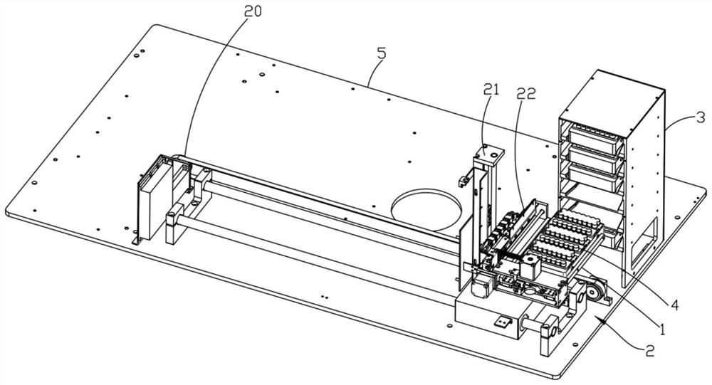
[0047] Such as Figure 1-4 As shown, a PCR chip tray transfer and storage mechanism in this embodiment includes: a mechanical gripper 1 for grabbing the chip tray 4, a three-dimensional drive mechanism 2 for driving the movement of the mechanical gripper 1, and a storage chip Storage bin 3 for pallet 4;

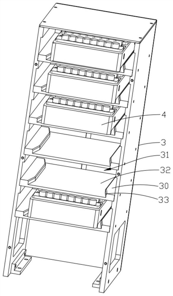
[0048] In the storage bin 3, several partitions 30 are used to separate and form several storage chambers 31 for storing chip trays 4 along the vertical direction;

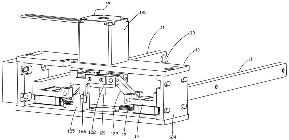
[0049] The mechanical gripper 1 includes a mounting base 10, two clamping rods 11 that can be slidably arranged on the mounting base 10 along the Y direction, and a jaw driving mechanism for driving the two clamping rods 11 to move along the Y direction to open or clamp 12. The three-dimensional driving mechanism 2 can drive the mechanical gripper 1 to move along the X direction to send the chip tray 4 on the mechanical gripper 1 into the storage chamber 31 . The mounting base 10 is provided with a jaw slide ra...

Embodiment 2

[0056] The difference between this embodiment and Embodiment 1 is only the jaw driving mechanism 12, refer to Figure 5-6 ,, In this embodiment, the jaw driving mechanism 12 includes a jaw motor 150 arranged on the mounting base 10, a cam 151 drivingly connected to the output shaft of the jaw motor 150, connected to the jaw slider 14 and positioned on the cam The friction wheel 152 on the side of 151 and the return spring 153 connected between the jaw slider 14 and the mounting seat 10;

[0057] The jaw motor 150 drives the cam 151 to rotate, and the friction wheel 152 is driven by the cam 151 to make the two jaw sliders 14 slide toward the side away from the cam 151 along the Y direction, driving the two clamping rods 11 to open; the two return springs 153 The two clamping jaw sliders 14 are set to generate an active force toward the cam 151, so that the clamping jaw sliders 14 slide back toward the direction of the cam 151 through the return spring 153, so as to realize the ...

Embodiment 3

[0060] refer to Figure 7-10 , as a further improvement on the basis of Embodiment 1 or 2, in this embodiment, the PCR chip tray transfer and storage mechanism also includes a base plate 5, and the three-dimensional drive mechanism 2 includes a Y-direction drive mechanism 20 arranged on the base plate 5, arranged on The Z-direction driving mechanism 21 on the Y-direction driving mechanism 20 and the X-direction driving mechanism 22 arranged on the Z-direction driving mechanism 21 , and the mechanical gripper 1 is arranged on the X-direction driving mechanism 22 .

[0061] Wherein, the Y-direction driving mechanism 20 includes a guide rod 200 arranged on the base plate 5 along the Y direction, a Y slider 201 slidably arranged on the guide rod 200, a Y motor 202 arranged on the base plate 5, and a connection between the Y motor 202 The Y driving pulley 203 drivingly connected to the output shaft, the Y driven pulley 205 drivingly connecting with the Y driving pulley 203 through ...


PUM


Abstract

The invention discloses a PCR chip tray transfer and storage mechanism. The PCR chip tray transfer and storage mechanism comprises a mechanical clamping jaw used for grabbing a chip tray, a three-dimensional driving mechanism used for driving the mechanical clamping jaw to move and a storage bin used for storing the chip trays, wherein the interior of the storage bin is divided by a plurality of partition plates to form a plurality of storage chambers used for storing the chip trays in the vertical direction; and the mechanical clamping jaw comprises a mounting base, two clamping rods slidably arranged on the mounting base in the Y direction, and a clamping jaw driving mechanism used for driving the two clamping rods to move in the Y direction in order to be opened or clamped. According to the PCR chip tray transfer and storage mechanism, the chip trays are stacked and stored in the vertical direction through the storage bin, so that the space occupied by storage can be reduced; and through the cooperation of the mechanical clamping jaw and the three-dimensional driving mechanism, the chip trays can be transferred and stored into the storage bin, or the chip trays in the storage bin can be taken out and transferred to designated positions, so that automatic transfer and storage of the chip trays can be realized, and the working efficiency is improved.

Description

technical field [0001] The invention relates to the field of biotechnology, in particular to a PCR chip tray transfer and storage mechanism. Background technique [0002] PCR chips are usually carried by special chip trays and need to be transferred or stored to meet the relevant needs of detection. At present, the storage of PCR chip trays usually adopts the method of horizontal tile storage, which has the disadvantage of taking up a large space and is not convenient for automatic storage. In addition, the transfer of PCR chip trays between the storage area and the target area sometimes requires manual or manual assistance, and the degree of automation is not high and the efficiency is low. [0003] Therefore, a more reliable solution is now needed. Contents of the invention [0004] The technical problem to be solved by the present invention is to provide a PCR chip tray transfer and storage mechanism for the above-mentioned deficiencies in the prior art. [0005] In ...

Claims


Application Information

Patent Timeline
IPC IPC(8): B65D25/04B65D25/02B65G47/90B65G35/00
CPCB65D25/04B65D25/02B65G47/90B65G35/00
Inventor 黄杰王弼陡刘亮许杰谭耀
Owner SUZHOU INST OF BIOMEDICAL ENG & TECH CHINESE ACADEMY OF SCI
Why Eureka
Try Eureka