Combined cast-in-place box girder support structure and construction method thereof

A support structure and combined technology, which is applied in the direction of infrastructure engineering, bridges, bridge construction, etc., can solve the problems of increased volume of sludge cleaning, increased volume of replacement materials, and increased costs

Pending Publication Date: 2021-05-11
中交二公局第六工程有限公司
View PDF0 Cites 3 Cited by
  • Summary
  • Abstract
  • Description
  • Claims
  • Application Information

AI Technical Summary

Problems solved by technology

If the area of ​​the fish pond is large, the volume of sludge removal and r...

Method used


Image

  • Combined cast-in-place box girder support structure and construction method thereof
  • Combined cast-in-place box girder support structure and construction method thereof
  • Combined cast-in-place box girder support structure and construction method thereof

Examples


Embodiment 1

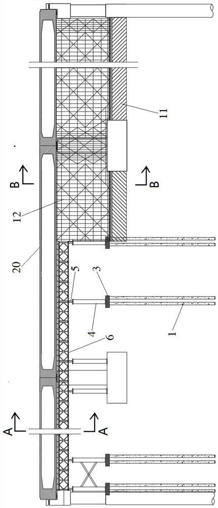
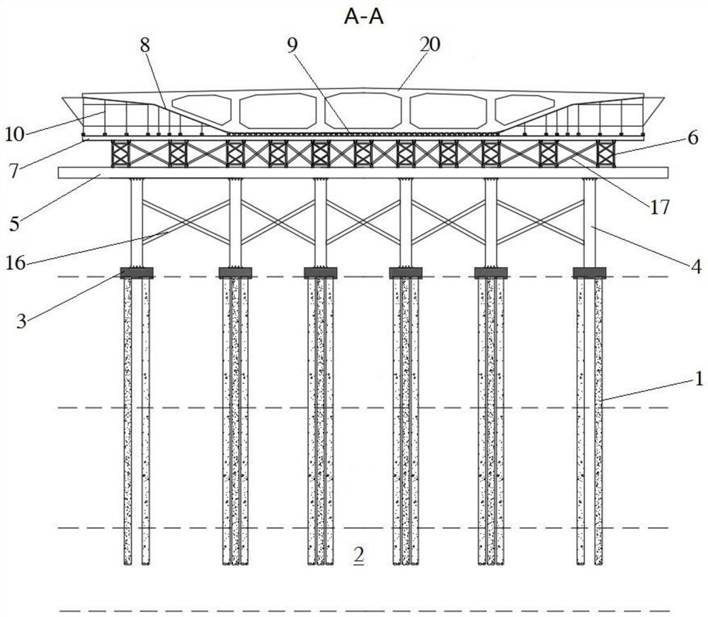
[0037] refer to figure 1 , figure 2 and image 3 , the embodiment of the present invention proposes a combined cast-in-place box girder support structure, which is used to cast-in-place box girder 20 for a large bridge. One section of the bridge spans a weak foundation, and the other section spans a hard ground. The pouring box girder support structure includes: multiple sets of prestressed pipe pile foundations 1, multiple steel pipe columns 4, formwork 8 and roadbed 11; multiple sets of prestressed pipe pile foundations 1 are distributed in the weak foundation along the bridge direction, and the The lower end goes deep into the fully weathered granite layer 2, and the upper end of each group of prestressed pipe pile foundations 1 is respectively provided with a concrete cap 3; each of the steel pipe columns 4 is respectively fixed on one of the concrete caps 3, and each row A load-bearing beam 5 is respectively fixed on the steel pipe column 4; a plurality of the Bailey f...

Embodiment 2

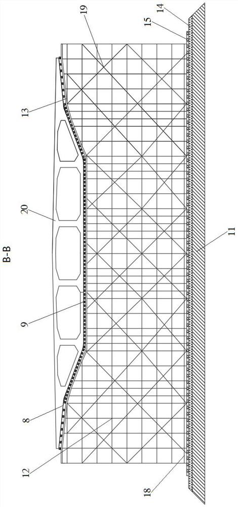
[0043] refer to figure 2 and image 3 A gravel layer 14 is laid on the road bed 11, and a concrete layer 15 is laid on the gravel layer 14.

[0044] The degree of compaction of the road bed 11 reaches more than 90%, the thickness of the gravel layer 14 is 30cm, the degree of compaction reaches more than 95%, and the concrete layer 15 is C15 concrete with a thickness of 15cm.

Embodiment 3

[0046] refer to figure 2 , on the basis of Embodiment 2, a first scissor brace 16 is connected between every two horizontally adjacent steel pipe columns 4 .

[0047]The first scissors braces 16 are arranged in the transverse bridge direction of the steel pipe piles 4 to laterally reinforce the steel pipe columns 4, and the first scissors braces 16 are made of I20a engineering steel.


PUM

PropertyMeasurementUnit
Thicknessaaaaaaaaaa

Abstract

The invention provides a combined cast-in-place box girder support structure. The combined cast-in-place box girder support structure comprises a prestressed pipe pile foundation, a steel pipe column, a formwork and a roadbed, wherein multiple sets of prestressed pipe pile foundations are distributed in a soft foundation in an array mode, lower ends of the prestressed pipe pile foundations penetrate into a fully-weathered granite layer, and a concrete bearing platform is arranged at an upper end of each set of prestressed pipe pile foundation; each steel pipe column is fixed on one concrete bearing platform, and a bearing beam is fixed on each row of steel pipe columns; a plurality of bailey trusses are lapped on the bearing beams, and a plurality of distribution beams are transversely carried on the bailey trusses; the formwork comprises a bottom plate and side plates, a plurality of square timbers are arranged between the bottom plate and the distribution beams in the bridge direction, and side formwork supporting frames are arranged between the side plates and the distribution beams; the roadbed is located on the hard ground, a bowl-buckle-type full framing is built on the roadbed, a jacking plate is arranged on the upper portion of the bowl-buckle-type full framing, and a plurality of square timbers are arranged between the jacking plate and a bottom plate and a side plate of the formwork in the bridge direction. The invention further provides a construction method of the combined cast-in-place box girder support.

Description

technical field [0001] The invention belongs to the field of bridge construction, and in particular relates to a combined cast-in-place box girder support structure and a construction method thereof. Background technique [0002] When constructing cast-in-place box girders for long-span bridges, brackets need to be erected, and the foundation needs to be ensured to be stable. If a part of the bridge spans a large area of ​​weak ground such as fish ponds, it is generally necessary to clean up all the silt in the fish ponds , and all of them are replaced with gravel materials with good water properties for building coating, and layered rolling is carried out until the compaction degree reaches more than 95%, and finally concrete is laid on the surface of the compacted filler to harden. If the area of ​​the fish pond is large, the volume of silt cleaning and replacement materials will increase greatly, resulting in a sharp increase in cost. Contents of the invention [0003]...

Claims


Application Information

Patent Timeline
IPC IPC(8): E01D21/00E01D2/04E02D5/58E02D27/14
CPCE01D2/04E01D21/00E02D5/58E02D27/14
Inventor 张利斌马小龙陈连礼
Owner 中交二公局第六工程有限公司
Why Eureka
Try Eureka