
Method and system for measuring multi-dimensional gap of U-shaped groove

A measurement method, U-shaped groove technology, applied in the direction of mechanical gap measurement, greenhouse gas reduction, climate sustainability, etc., can solve the problem of large measurement impact, increase the identification of fixed-point marks, limit the breadth and depth of high-precision digital gap measurement technology, etc. problem, to achieve the effect of strong self-adaptation and simple and convenient measurement method

Active Publication Date: 2021-05-11
CHINA GENERAL NUCLEAR POWER OPERATION +2
View PDF5 Cites 0 Cited by
  • Summary
  • Abstract
  • Description
  • Claims
  • Application Information

AI Technical Summary

Problems solved by technology

[0004] For the application scenario of measuring multiple gaps in U-shaped grooves, the mainstream products in the market now include laser beam edge detection products, laser triangulation products, and 3D structured light products. Although they can meet the high-precision digital measurement of general gaps, they are more or less Rarely there are one or some of the following defects: 1. Additional identification of fixed-point marks; 2. Require equipment to shoot on both sides of the measured object; 3. Only single object / single-dimensional gap measurement; 4. Application environment ( Light, occlusion, radiation, etc.) have a great influence on the measurement
This greatly limits the breadth and depth of the application of high-precision digital gap measurement technology in engineering

Method used


Image

  • Method and system for measuring multi-dimensional gap of U-shaped groove
  • Method and system for measuring multi-dimensional gap of U-shaped groove
  • Method and system for measuring multi-dimensional gap of U-shaped groove

Examples


Embodiment Construction

[0049] The following will clearly and completely describe the technical solutions in the embodiments of the present invention with reference to the accompanying drawings in the embodiments of the present invention. Obviously, the described embodiments are only some, not all, embodiments of the present invention. Based on the embodiments of the present invention, all other embodiments obtained by persons of ordinary skill in the art without making creative efforts belong to the protection scope of the present invention.

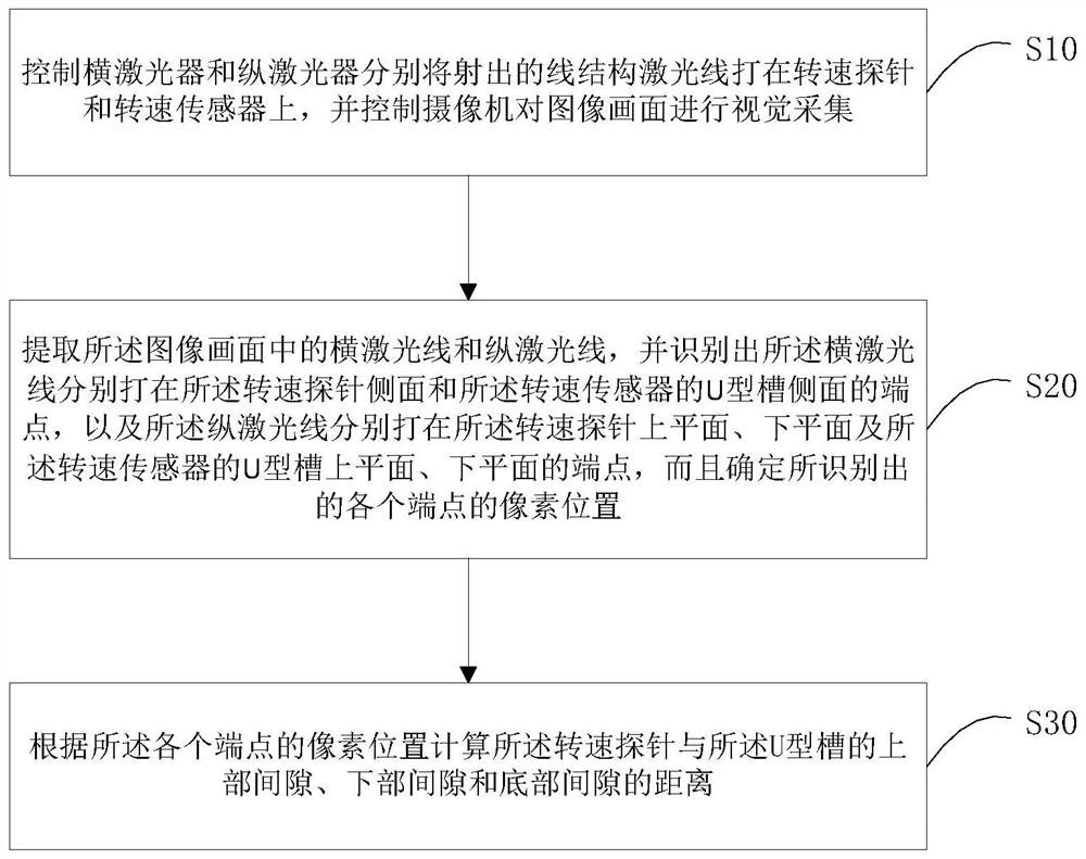
[0050] figure 2 It is a flow chart of Embodiment 1 of the U-shaped groove multi-dimensional gap measurement method of the present invention. The U-shaped groove multi-dimensional gap measurement method of this embodiment can be applied to the installation of the main pump speed sensor on the main pump, which can realize fast and accurate measurement The multi-dimensional gap of the U-shaped groove greatly improves the work efficiency, shortens the main line p...


PUM


Abstract

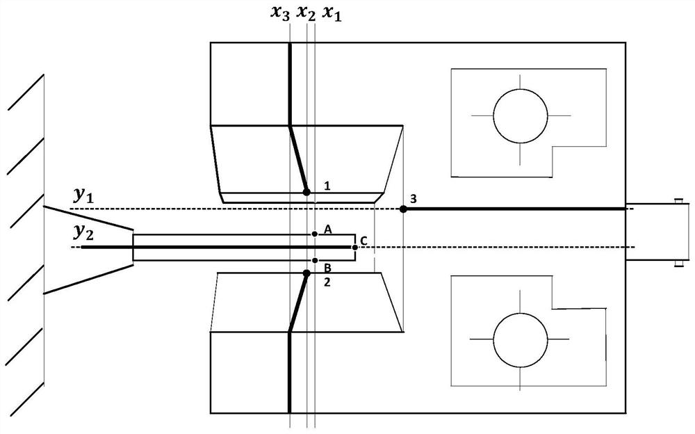
The invention relates to a method and system for measuring a multi-dimensional gap of a U-shaped groove, and the method comprises the steps: controlling a transverse laser device and a longitudinal laser device to emit line structure laser lines on a rotating speed probe and a rotating speed sensor, and controlling a camera to carry out the visual collection of an image; extracting transverse laser rays and longitudinal laser rays in the image picture, and identifying the end points of the transverse laser rays respectively hit on the side surface of the rotating speed probe and the side surface of the U-shaped groove of the rotating speed sensor, and the end points of the longitudinal laser rays respectively hit on the upper plane and the lower plane of the rotating speed probe and the upper plane and the lower plane of the U-shaped groove of the rotating speed sensor; determining the pixel position of each identified end point; and calculating the distances from the rotating speed probe to the upper gap, the lower gap and the bottom gap of the U-shaped groove according to the pixel position of each end point. By implementing the technical scheme of the invention, multi-dimensional and high-precision measurement of the U-shaped groove gap is realized; additional identification fixed point marks are not needed; and the measurement mode is simple.

Description

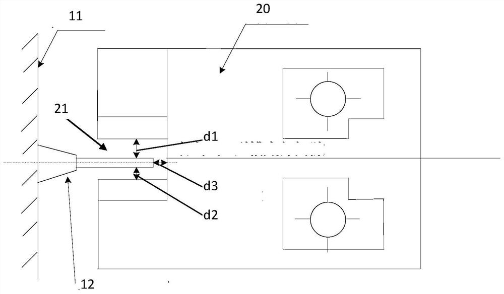
technical field [0001] The invention relates to the field of instrument control, in particular to a method and system for measuring U-shaped groove multi-dimensional gaps. Background technique [0002] With the development and deepening of applications such as precision manufacturing, precision installation, and precision measurement, the demand for high-precision digital measurement of gaps in many fields is becoming more and more widespread and urgent. For example, measuring instruments such as speed have high precision requirements for installation clearances. [0003] figure 1 It is a schematic diagram of the installation of the speed measuring instrument. The speed probe 12 of the main pump is fixed on the shaft 11 of the main pump and can rotate with the shaft 11 of the main pump. The rotational speed measuring instrument is used to detect the rotational speed of the main pump. The rotational speed sensor 20 of the rotational speed measuring instrument is fixed on th...

Claims


Application Information

Patent Timeline
Patent Type & Authority Applications(China)
IPC IPC(8): G01B5/14
CPCG01B5/14Y02E30/30
Inventor 陈永伟索凌平邱河文邹克峰何思源周小维胥籽任
Owner CHINA GENERAL NUCLEAR POWER OPERATION
Learn More