Precise measurement method for free bending forming size of pipe plane

A technology of bending forming and measuring method, applied in the direction of measuring devices, instruments, and optical devices, etc., can solve the problems of limited surface area of ​​flat projectors, large size limitations of elbow fittings, and difficulty in guaranteeing measurement accuracy, and achieves good results. The effect of promoting application value, filling industry gaps, and improving accuracy

Active Publication Date: 2021-05-11
NANJING UNIV OF TECH
View PDF6 Cites 3 Cited by
  • Summary
  • Abstract
  • Description
  • Claims
  • Application Information

AI Technical Summary

Problems solved by technology

However, due to the influence of the rotation angle of the side head, the three-dimensional coordinate measuring instrument cannot realize three-dimensional 360-degree omnidirectional measurement, and in many cases cannot scan the full three-dimensional pipe shape; although the plane projector can better project the contour of the bent pipe on the plane , to facilitate the measurement of the bending radius and bending angle of the pipe fittings, but due to the limited area of ​​the plane projector, the size of the measuring bend pipe fittings is limited, and it cannot be measured for slightly larger bends; the vernier universal angle ruler can be directly used to measure The measurement of the angle of the pipe fittings, but because it is difficult to ensure that the measuring arm of the angle ruler fits accurately with the ridges on both sides of the straight section of the elbow during actual operation, the measurement accuracy is difficult to guarantee

Method used


Image

  • Precise measurement method for free bending forming size of pipe plane
  • Precise measurement method for free bending forming size of pipe plane
  • Precise measurement method for free bending forming size of pipe plane

Examples


Embodiment Construction

[0041] The present invention will be described in detail below in conjunction with the accompanying drawings and embodiments, but this should not be used as a limitation to the protection scope of the present application.

[0042] A method for accurately measuring the dimensions of free-bending pipes in a flat plane, characterized in that the method comprises the following steps:

[0043] Step 1: Scan the actual planar elbow with a scanner to generate a point cloud image of the entire pipe, and generate a solid elbow model after surface fitting the point cloud image;

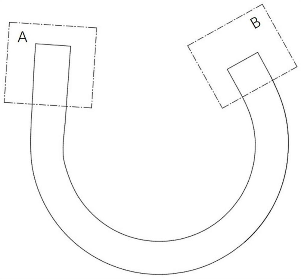
[0044] The curved pipe model is projected to obtain the contour line of the straight line segment A before the bending starting point and the straight line segment B after the bending cutoff, such as figure 1 shown.

[0045] Step 2: Make an equidistant vertical line through the contour line, the vertical line is connected to the intersection point of the two contour lines, take the midpoints of all line segment...


PUM


Abstract

The invention provides a precise measurement method for the free bending forming size of a pipe plane, and the method is characterized in that the method comprises the steps: scanning a plane bent pipe, generating a point cloud picture, and generating a solid model after fitting; projecting a straight-line section part A before the bending starting point and a straight-line section part B after bending is stopped to obtain a contour line of the straight-line section part A and the straight-line section part B; making ten equidistant vertical lines to pass through the contour lines, connecting the vertical lines with intersection points of the two contour lines, taking midpoints of all line segments for straight line fitting, and obtaining central axes LA and LB; establishing a new coordinate system X1Y1Z1; calculating to obtain a conversion matrix M of a new coordinate system and an old coordinate system, projecting LB to X1O1Z1 after data point conversion to obtain a rotation angle theta around an X1 axis, and converting to obtain a new data point; and outputting an X1O1Z1 front view to obtain the contour line of the whole pipe fitting. The measuring method provided by the invention can obtain the central axis of the plane bent pipe in actual machining, and the bending radius and the bending angle of the bent pipe are obtained through the central axis, so that the accuracy of measuring the important size of the bent pipe is improved, and the industry blank is filled.

Description

technical field [0001] The invention relates to a method for accurately measuring the dimensions of free-bending pipes, in particular to a method for accurately measuring the dimensions of free-bending pipes in actual processing. Background technique [0002] Bending pipe is an important component widely used in various fields of industry. It is easy to meet the urgent requirements of light weight and toughening products in the field of advanced plastic forming. It has a wide range of applications in aerospace, automobile, rail transit and other fields. However, after the bending forming process of the pipe is completed, the elastic deformation in the deformation area of ​​the elbow is unloaded, which causes the pipe to rebound, and the stress state inside and outside the elbow is opposite. The radius increases and the bend angle decreases. The bending radius and bending angle of the elbow after springback deviate from the bending radius and bending angle before springback,...

Claims


Application Information

Patent Timeline
Patent Type & Authority Applications(China)
IPC IPC(8): G01B11/00
CPCG01B11/002
Inventor 王华谢媛媛徐振华
Owner NANJING UNIV OF TECH
Why Eureka
Try Eureka