
Computer CPU-GPU shared cache control method and system

A CPU-GPU, shared cache technology, applied in memory systems, computing, program control design, etc., can solve the problems of complex dynamic adjustment process, waste of valuable system resources, and inability to adjust in time.

Active Publication Date: 2021-05-11
湖南中科长星科技有限公司
View PDF6 Cites 0 Cited by
  • Summary
  • Abstract
  • Description
  • Claims
  • Application Information

AI Technical Summary

Problems solved by technology

However, the static allocation method cannot adjust in time because the allocated LLC is fixed. Although the dynamic allocation method realizes dynamic adjustment, the existing dynamic adjustment process is complicated, and the adjustment process wastes valuable system resources.

Method used


Image

  • Computer CPU-GPU shared cache control method and system
  • Computer CPU-GPU shared cache control method and system

Examples


Embodiment 1

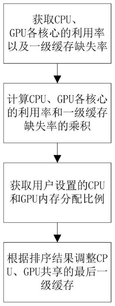
[0036] In one embodiment, the present invention provides a computer CPU-GPU shared cache control method, applied in the CPU-GPU fusion architecture, comprising the following steps:

[0037] Obtain the utilization rate of each core of the CPU and the miss rate of the first-level cache, and the utilization rate of each core of the GPU and the miss rate of the first-level cache;

[0038] Calculate the product of the utilization rate of each core of the CPU and the miss rate of the first-level cache, and obtain C n , n=1,...,N; Calculate the product of the utilization rate of each GPU core and the first-level cache miss rate, and get G m , m=1,...,M; wherein, N is the number of CPU cores, and M is the number of GPU cores;

[0039] Get the CPU and GPU memory allocation ratio set by the user, according to the ratio and C n , G m get C' n , G' m , and for C' n , G' m put in order;

[0040] Adjust the last-level cache shared by CPU and GPU according to the sorting results.

...

Embodiment 2

[0065] In another embodiment, the present invention also provides a computer CPU-GPU shared cache control system, which is applied in the CPU-GPU fusion architecture, wherein the method includes the following modules:

[0066] The first obtaining module is used to obtain the utilization rate of each core of the CPU and the miss rate of the first-level cache, and the utilization rate of each core of the GPU and the miss rate of the first-level cache;

[0067] The calculation module is used to calculate the product of the utilization rate of each core of the CPU and the first-level cache miss rate to obtain C n , n=1,...,N; Calculate the product of the utilization rate of each GPU core and the first-level cache miss rate, and get G m , m=1,...,M; wherein, N is the number of CPU cores, and M is the number of GPU cores;

[0068] The second obtaining module is used to obtain the CPU and GPU memory allocation ratio set by the user, according to the ratio and C n , G m get C' n ,...

Embodiment 3

[0075] In addition, in another embodiment, the present invention also provides a computer-readable storage medium for storing computer program instructions, which is characterized in that, when the computer program instructions are executed by a processor, the computer program instructions described in Embodiment 1 are implemented. Methods.


PUM


Abstract

The invention provides a computer CPU-GPU shared cache control method and system, and the method comprises the steps of firstly obtaining the utilization rate of each core of a CPU and a GPU and a first-level cache missing rate; calculating the product of the utilization rate of each core of the CPU and the GPU and the first-level cache missing rate; obtaining a CPU and GPU memory allocation proportion set by a user; and adjusting the last level of cache shared by the CPU and the GPU according to the sorting result. According to the method provided by the invention, dynamic adjustment of the LLC is realized through the utilization rate of each core and the first-level cache missing rate in combination with setting of a user, the problems that the LLC adjustment is too complicated and system resources are wasted in the prior art are solved, the LLC in a computer is optimized and adjusted in a targeted manner, and the overall performance of a CPU chip integrated with a GPU is improved.

Description

technical field [0001] The present application relates to the field of computer chips, in particular to a control method and system for CPU-GPU shared last-level cache. Background technique [0002] The cache is a high-speed memory located between the CPU and the memory. When the CPU reads data, it will first look in the cache. If it is found, it will read the data immediately, otherwise it will be read from the relatively slow memory. Reasonably set the cache Can increase the speed of the CPU. Before the use of the GPU, the CPU was responsible for all the affairs of the computer. Later, a GPU dedicated to graphics processing and floating-point calculations, that is, a graphics processor, appeared. Since the GPU and the CPU are connected through the PCI-e bus, data transmission has become a process between the GPU and the CPU. Bottleneck of data exchange. With the development of large-scale integrated circuits, more and more electronic components are integrated on the chip...

Claims


Application Information

Patent Timeline
Patent Type & Authority Applications(China)
IPC IPC(8): G06F12/084G06F9/50
CPCG06F12/084G06F9/5016Y02D10/00
Inventor 于慧
Owner 湖南中科长星科技有限公司
Learn More