Method for calculating thickness of blank shell at position of continuous casting roller row and solidification tail end of casting machine

A technology of solidification end and continuous casting roll, applied in special data processing applications, geometric CAD, design optimization/simulation, etc., can solve the problems of inaccurate calculation, affecting the accuracy of calculation results, calculation process adaptability, slow calculation speed, etc.

Pending Publication Date: 2021-05-11
JIANGYIN XINGCHENG SPECIAL STEEL WORKS CO LTD
View PDF0 Cites 3 Cited by
  • Summary
  • Abstract
  • Description
  • Claims
  • Application Information

AI Technical Summary

Problems solved by technology

[0003] There are also many difficulties in using mathematical models. The modeling process from scratch requires a team of talents who are not only proficient in continuous casting and solidification expertise, but also have proficient programming capabilities. The programming process usually takes several years; Whether the model is suitable for the current casting machine (square, round, plate type, specifications, etc.) and whether the physical parameters are a

Method used


Image

  • Method for calculating thickness of blank shell at position of continuous casting roller row and solidification tail end of casting machine
  • Method for calculating thickness of blank shell at position of continuous casting roller row and solidification tail end of casting machine
  • Method for calculating thickness of blank shell at position of continuous casting roller row and solidification tail end of casting machine

Examples


Embodiment Construction

[0014] The present invention will be further described in detail below in conjunction with the accompanying drawings and embodiments.

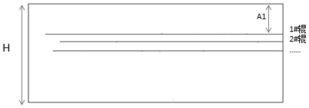
[0015] For example: for a steel billet of 200×200 square meters, the distance between the inner and outer arcs is H=195mm measured on a low magnification, and the positions of the roll rows are 13.5 meters for 1# roller, 15 meters for 2# roller, and 16.5 meters for 3# roller; continuous casting The casting speed is 1.2 m / min; it is known that the slab length is low. Solve the billet shell thickness at each roll of the steel in this process of continuous casting machine and the solidification end position when it is fully solidified.

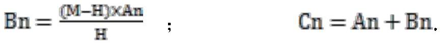
[0016] According to the known conditions, that is, the nominal thickness of the slab is M=200mm, and the thickness of the slab at the low multiple is H=195mm;

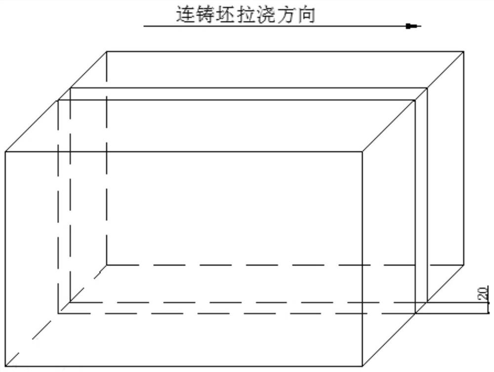
[0017] Cut a continuous casting slab low-magnification sample with a length equivalent to the cross-sectional size of the casting slab, saw along the ce...


PUM


Abstract

The invention relates to a method for calculating the thickness of a slab shell at the position of a continuous casting roller row and the solidification tail end of a casting machine. The method is characterized by comprising the following steps: according to a rule that zero plasticity temperature is approximately equal to solidus temperature, acquiring the thickness of the slab shell at the position of a pulling-straightening roller by searching point-shaped cracks on a low magnification of a continuous casting slab and measuring the distance from the cracks to the edge part of the casting slab; and according to the measured thickness of the slab shell at the position of a roller farthest from the meniscus, the position of a corresponding roller row and a pulling speed, further reckoning the comprehensive solidification coefficient and the liquid phase cavity length of the casting machine through secondary application of a solidification law square root formula, so that the effect of nail shooting or solidification model calculation is achieved. The invention discloses the method which does not need a model, does not need nail shooting and deduces the thickness of the slab shell and the solidification tail end by researching the low power of the continuous casting slab, and the method can optimize tail end electromagnetic stirring, soft reduction tool arrangement and a production process, so that the segregation problem of the continuous casting billet and a rolled material is solved.

Description

technical field [0001] The invention belongs to the technical field of metal smelting, and in particular relates to a method for calculating the shell thickness of continuous casting rolls and the solidification end of a casting machine. Background technique [0002] Segregation, especially central segregation, is an important indicator for the quality evaluation of steel materials, especially special steel, and poor segregation control will seriously harm the performance of steel processed products. In order to improve the central segregation, the continuous casting machine is usually equipped with electromagnetic stirring at the end and light reduction equipment. However, it usually takes a long time for many iron and steel enterprises to debug these equipments, and some have not found a suitable process for many years. The improvement of segregation cannot be achieved. to the expected effect. The reason is mainly that the position of the solidification end or the thickne...

Claims


Application Information

Patent Timeline
IPC IPC(8): G06F30/17G06F30/20B22D11/16
CPCB22D11/16G06F30/17G06F30/20
Inventor 任一峰饶立华许晓红葛洪硕白云柳琴马晓东
Owner JIANGYIN XINGCHENG SPECIAL STEEL WORKS CO LTD
Why Eureka
Try Eureka