Electromagnet protection circuit

A technology for protecting circuits and electromagnets, applied in the direction of electromagnets, circuits, electromagnets, etc. The effect of avoiding personal danger

Pending Publication Date: 2021-05-11
WARRENWELL HIGH TECH
View PDF0 Cites 0 Cited by
  • Summary
  • Abstract
  • Description
  • Claims
  • Application Information

AI Technical Summary

Problems solved by technology

[0002] Electromagnets are widely used in various electronic circuit fields, and because they generate suction when energized, they can convert electrical energy into mechanical energy, so they can also be used for on-off circuits and electronic switches of various mechanical structures; but usually If the coil-wound electromagnet used is not equipped with a suitable protection circuit, when the control signal fails and the control circuit connected to it continues to conduct, it will cause the electromagnet to have a continuous current passing through, resulting in electromagnetic The iron overheats and destroys itself, even causing personal danger

Method used


Image

  • Electromagnet protection circuit

Examples


Embodiment Construction

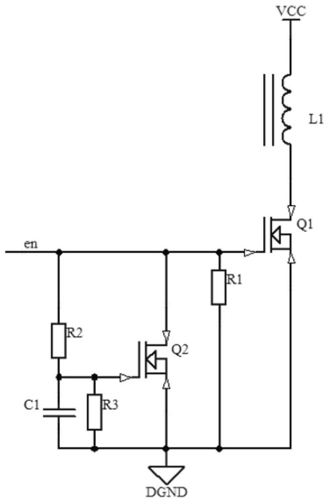
[0012] The technical solutions in the embodiments of the present invention will be clearly and completely described below with reference to the accompanying drawings in the embodiments of the present invention.

[0013] like figure 1 As shown, an electromagnet protection circuit of the present invention is connected to the control signal input end en of the control circuit, the electromagnet protection circuit includes an electromagnet L1, and the electromagnet protection circuit also includes MOS transistors Q1, Q2, resistors R1-R3 , Capacitor C1, in which the RC charging circuit is composed of resistor R2 and capacitor C1; one end of electromagnet L1 is connected to power supply VCC, the other end of electromagnet L1 is connected to the drain of MOS transistor Q1, the gate of MOS transistor Q1 is connected to resistors R1, One end of R2 and the drain of the MOS transistor Q2 are all connected to the control signal input end en of the control circuit. The gate of the MOS tran...


PUM

PropertyMeasurementUnit
electrical resistanceaaaaaaaaaa

Abstract

The invention provides an electromagnet protection circuit which can avoid the situation that an electromagnet is damaged due to continuous electrification and overheating when a control signal breaks down, so that potential safety hazards are eliminated, and personal danger is avoided. The electromagnet protection circuit is connected with a control signal input end of a control circuit, the electromagnet protection circuit comprises an electromagnet L1, MOS tubes Q1 and Q2, resistors R1 to R3 and a capacitor C1, one end of the electromagnet L1 is connected with a power supply VCC, the other end of the electromagnet L1 is connected with a drain electrode of the MOS tube Q1, a grid electrode of the MOS tube Q1 is connected with one end of the resistor R1, one end of the resistor R2 and a drain electrode of the MOS tube Q2 and then is connected to a control signal input end of the control circuit, a grid electrode of the MOS tube Q2 is connected with the other end of the resistor R2, one end of the capacitor C1 and one end of the resistor R3, and source electrodes of the MOS tube Q1 and the MOS tube Q2 are connected with the other ends of the resistor R1, the resistor R3 and the capacitor C1 and then are grounded.

Description

technical field [0001] The invention relates to the technical field of electronic circuits, in particular to an electromagnet protection circuit. Background technique [0002] Electromagnets are widely used in various electronic circuit fields, and because they generate suction when energized, they can convert electrical energy into mechanical energy, so they can also be used for circuit on-off and electronic switches of various mechanical structures; but usually The coil-wound electromagnet used is used without proper protection circuit. When the control signal fails and the control circuit connected to it continues to conduct, it will cause continuous current to pass through the electromagnet, resulting in electromagnetic failure. The iron overheats destroys itself and even causes personal danger. SUMMARY OF THE INVENTION [0003] In view of the above problems, the present invention provides an electromagnet protection circuit, which can avoid the situation that the ele...

Claims


Application Information

Patent Timeline
Patent Type & Authority Applications(China)
IPC IPC(8): H01F7/18
CPCH01F7/1844H01F2007/1866
Inventor 刘冰华坚陆叶青潘一鸣
Owner WARRENWELL HIGH TECH
Why Eureka
Try Eureka