
Three-dimensional positioning method for automatic slagging-off of desulfurized molten iron

A technology of three-dimensional positioning and desulfurization of molten iron, applied in the field of metallurgy, can solve the problems of different, prolonged production cycle, unstable slag removal effect, etc.

Inactive Publication Date: 2021-05-14
ANGANG STEEL CO LTD
View PDF8 Cites 2 Cited by
  • Summary
  • Abstract
  • Description
  • Claims
  • Application Information

AI Technical Summary

Problems solved by technology

[0002] In the field of industrial production, the desulfurization area of ​​converter steelmaking uses a ferry car with a tilting function to operate. The molten iron tank is placed on the tipping car, and then it is transferred to the injection position for injection operation. Tilt the tank body to the position where it can remove slag. During the slag removal process, since the conditions of each molten iron tank filled with molten iron are different, the amount of slag hanging in each molten iron tank is also different. The operator tilts the molten iron tank After arriving at the position, operate the slag removal machine to carry out the slag removal operation, because the slag removal effect is unstable during the manual slag removal operation, often the removal is not clean or the removal rate is high, and the slag removal time is long, resulting in waste of molten iron and at the same time causing The process requires further processing, prolonging the production cycle

Method used


Image

  • Three-dimensional positioning method for automatic slagging-off of desulfurized molten iron
  • Three-dimensional positioning method for automatic slagging-off of desulfurized molten iron
  • Three-dimensional positioning method for automatic slagging-off of desulfurized molten iron

Examples


Embodiment Construction

[0027] The specific embodiments provided by the present invention will be described in detail below in conjunction with the accompanying drawings.

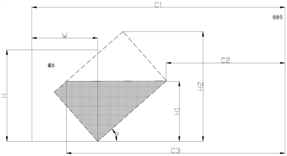
[0028] Such as figure 1 As shown, a three-dimensional positioning method for automatic slag removal of desulfurized molten iron comprises the following steps:

[0029] Step 1. Establish the original data model

[0030] 3) Calculate the minimum lifting height H1 and the maximum lifting height H2 of the slag remover

[0031] Install a set of encoders to measure the inclination angle of the molten iron tank on the output shaft of the reducer of the tank body of the molten iron car, tilt the molten iron tank to the position where the molten iron can be slag removed, and the angle acquisition value of the tank inclination angle encoder is fed back into the first-level PLC calculation The height of the molten iron level H1, that is, the minimum lifting height of the slag picker H1:

[0032] Minimum lifting height: H1=H sinα

[0033]...


PUM


Abstract

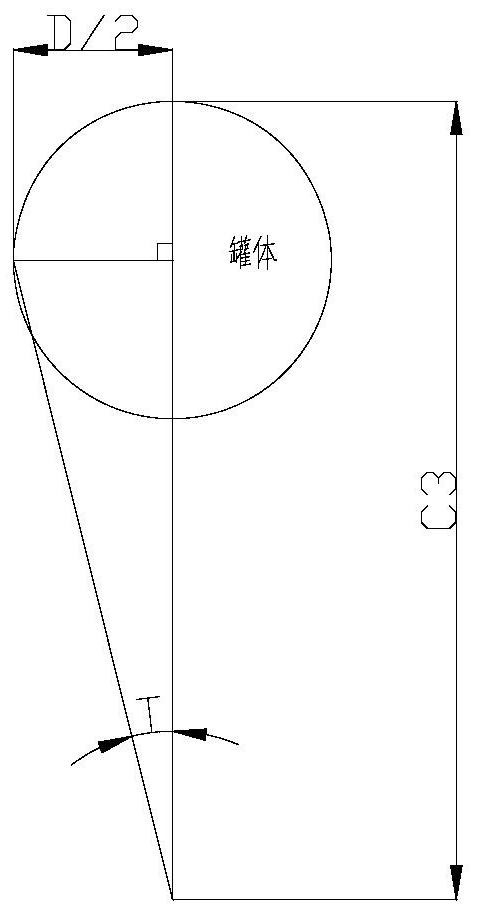
The invention provides a three-dimensional positioning method for automatic slagging-off of desulfurized molten iron. The method comprises the following steps of establishing an original data model, calculating the minimum lifting height H1, the maximum lifting height H2, the minimum extension distance C2, the maximum extension distance C3 and the rotation angle value T of a slagging-off machine, and sequentially controlling the lifting height, the rotation angle and the extension length of the slagging-off machine according to the calculated data to carry out automatic slagging-off operation. The situation that errors are too large during manual operation and the slagging-off effect is sometimes good or sometimes bad is avoided, the influence of personal errors on the slagging-off effect is reduced, the inclination angle of a tank body during slagging-off is determined, three-dimensional coordinates needing to act of the slagging-off machine are calculated through a certain method, and the slagging-off operation is carried out according to the set coordinates; and meanwhile, the three-dimensional coordinates are continuously changed, an area needing slagging-off is determined, automation of the slagging-off process is achieved, manual participation is reduced, the slagging-off efficiency is improved, the workload of workers is reduced, and harm caused by molten iron spray explosion to operators in the slagging-off process is reduced.

Description

technical field [0001] The invention relates to the technical field of metallurgy, in particular to a three-dimensional positioning method for automatic deslagging of desulfurized molten iron. Background technique [0002] In the field of industrial production, the desulfurization area of ​​converter steelmaking uses a ferry car with a tilting function to operate. The molten iron tank is placed on the tipping car, and then it is transferred to the injection position for injection operation. Tilt the tank body to the position where it can remove slag. During the slag removal process, since the conditions of each molten iron tank filled with molten iron are different, the amount of slag hanging in each molten iron tank is also different. The operator tilts the molten iron tank After arriving at the position, operate the slag removal machine to carry out the slag removal operation, because the slag removal effect is unstable during the manual slag removal operation, often the r...

Claims


Application Information

Patent Timeline
Patent Type & Authority Applications(China)
IPC IPC(8): C21C7/064C21C7/00
CPCC21C7/064C21C7/0087C21C2300/06Y02P10/25
Inventor 彭东东刘杨陈智勇马宁王涛王建昌林学斌刘晓琳王晓燕吕度钢李秋阳阚慧鹏
Owner ANGANG STEEL CO LTD
Learn More