Construction method of measuring pile structure for laneway measuring control point

A technology of measurement control and construction method, applied in measurement devices, measurement instruments, earthwork drilling, etc., can solve problems such as disturbance of surrounding rock in wells and roadways, influence on stable installation of measurement instruments, influence on measurement work, etc., so as to ensure smooth development and promote The effect of reducing the condensation rate of the hydration reaction and the influence of disturbance

Pending Publication Date: 2021-05-14
GUIZHOU JINFENG MINING
View PDF0 Cites 0 Cited by
  • Summary
  • Abstract
  • Description
  • Claims
  • Application Information

AI Technical Summary

Problems solved by technology

[0002] In the production process of underground mines, underground surveying work is the basis of underground safety production and engineering construction. When surveyors perform surveying work in mine engineering, shaft engineering, underground engineering, and tunnel engineering, the measurement control points are generally set at the roadway. At the top, the required instruments and equipment generally include prisms, two pairs of instrument tripods, a measuring total station, a prism base, and several auxiliary tools such as ladders and tool kits. First of all, it is necessary to select the placement position of these instruments and equipment, that is, the measurement control point, then fix the required measuring instruments at the points of the measuring instruments, and then adjust their posture to the required posture before aligning and then carrying out the measurement work, however, there are a lot of staff and mobile equipment in the shaft, and these personnel and equipment are likely to cause disturbance to the surrounding rock (4) of the shaft when they move back and forth, and then rub against the measuring instruments installed at the measurement control points, affecting the stability of the measuring instruments installation, and had an impact on the later measurement work

Method used


Image

  • Construction method of measuring pile structure for laneway measuring control point

Examples


Embodiment Construction

[0021] The technical solution of the present invention is further described below, but the scope of protection is not limited to the description.

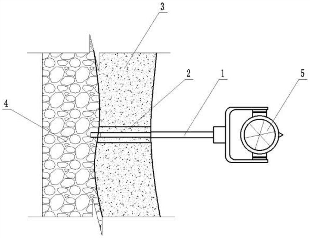
[0022] like figure 1 As shown, the present invention provides a kind of construction method of surveying pile structure with measuring control point in shaft roadway, comprises the following steps:

[0023] Step 1: Drill installation holes at the user-preset shaft measurement control points;

[0024] Step 2: Provide a measuring instrument, fix a supporting rod 1 on the measuring device, first insert the supporting rod 1 axially into the surrounding rock 4 of the shaft along the installation hole in step 1, and then soak the surroundings of the installation hole with water After the surrounding rock 4, apply marble glue on the surrounding rock 4 around the opening of the installation hole and make the outer peripheral surface of the support rod 1 exposed outside the opening of the installation hole consolidated with the surrounding...


PUM

PropertyMeasurementUnit
Apertureaaaaaaaaaa
Depthaaaaaaaaaa

Abstract

The invention provides a construction method of a measuring pile structure for a laneway measuring control point. The construction method comprises the following steps of drilling a mounting hole in the laneway measuring control point preset by a user, providing a measuring instrument, fixedly connecting a supporting rod to the measuring instrument, axially inserting the supporting rod into the surrounding rock of the laneway along the mounting hole, and then wetting the surrounding rock around the opening of the mounting hole with water, thensmearing marble glue on surrounding rock around the opening of the mounting hole, fixedly connecting the peripheral face, exposed out of the opening of the mounting hole, of the supporting rod with the surrounding rock of the laneway through the marble glue, and forming an adhesive body after the marble glue is coagulated, and spraying the cement mortar on the roadway surrounding rock on the periphery of the glue body to form a guniting body. With the adoption of the technical scheme, the surrounding rock is infiltrated before the marble glue is smeared, so that the coagulation of the marble glue and the cement mortar is promoted, the measuring instrument can be stably supported on the surrounding rock and is prevented from being scratched or disturbed by personnel or equipment, and a foundation is laid for carrying out measuring work.

Description

technical field [0001] The invention belongs to the technical field of mine measurement equipment, and in particular relates to a construction method of a measurement pile structure for a measurement control point of a shaft. Background technique [0002] In the production process of underground mines, underground surveying work is the basis of underground safety production and engineering construction. When surveyors perform surveying work in mine engineering, shaft engineering, underground engineering, and tunnel engineering, the measurement control points are generally set at the roadway. At the top, the required instruments and equipment generally include prisms, two pairs of instrument tripods, a measuring total station, a prism base, and several auxiliary tools such as ladders and tool kits. First of all, it is necessary to select the placement position of these instruments and equipment, that is, the measurement control point, then fix the required measuring instrumen...

Claims


Application Information

Patent Timeline
IPC IPC(8): G01C15/00E21F17/18
CPCE21F17/18G01C15/00
Inventor 刘伦高猛江王能跃郑禄璟吴岩佩金开玥陈建新
Owner GUIZHOU JINFENG MINING
Why Eureka
Try Eureka