Hot air supply rapid adjusting system for icing wind tunnel and air supply method

A technology for adjusting the system and hot gas, which is applied in the field of wind tunnel testing, and can solve problems such as complex test procedures, slow stabilization time of model inlet temperature, and large flow changes

Active Publication Date: 2021-05-14
LOW SPEED AERODYNAMIC INST OF CHINESE AERODYNAMIC RES & DEV CENT
View PDF13 Cites 6 Cited by
  • Summary
  • Abstract
  • Description
  • Claims
  • Application Information

AI Technical Summary

Problems solved by technology

[0007] 3. When the real branch is opened, the simulated branch needs to be closed, which will cause a large flow change;
[0008] 4. For the test times that require multiple temperature adjustments, the existing hot gas supply system has to switch to the simulation branch again to repeat the test process, whi

Method used


Image

  • Hot air supply rapid adjusting system for icing wind tunnel and air supply method
  • Hot air supply rapid adjusting system for icing wind tunnel and air supply method
  • Hot air supply rapid adjusting system for icing wind tunnel and air supply method

Examples


Embodiment 1

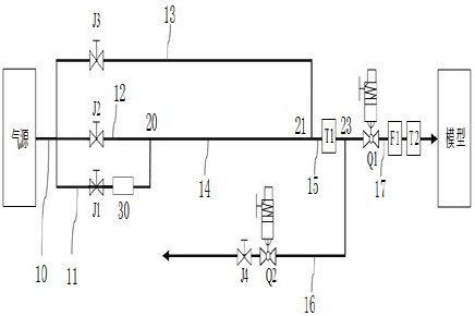
[0041] Such as figure 2Shown is a schematic diagram of a hot air supply rapid adjustment system for icing wind tunnels in Embodiment 1 of the present invention. A hot air supply rapid adjustment system for icing wind tunnels in Embodiment 1 of the present invention includes: Air source, air source main road 10, hot air branch 11, first cold air branch 12, second cold air branch 13, first mixing branch 14, second mixing branch 15, simulation branch 16, real branch 17, of which:

[0042] The inlet of the air source main road 10 is connected to the air source outlet, and the outlet of the air source main road 10 is simultaneously connected to the entrance of the hot air branch 11, the entrance of the first cold air branch 12, and the entrance of the second cold air branch 13. connect;

[0043] The gas source is used to generate the gas for the anti-icing test, and when the gas is generated from the gas source, it is in a state of natural temperature;

[0044] In order to spec...

Embodiment 2

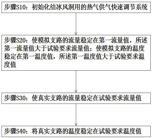
[0060] Such as image 3 Shown is a schematic diagram of the air supply method using the above-mentioned hot air supply quick adjustment system for the icing wind tunnel in Embodiment 2 of the present invention, which includes the following steps:

[0061] Step S10: Initialize the hot air supply rapid adjustment system for the icing wind tunnel;

[0062] Step S20: Stabilize the flow of the simulation branch 16 at a first flow value, the first flow value is greater than the test required flow value; stabilize the temperature of the simulation branch 16 at a first temperature value, the first temperature value is greater than Test required temperature value;

[0063] Step S30: Stabilize the flow of the real branch 17 at the test required flow value;

[0064] Step S40: Stabilize the temperature of the real branch 17 at a temperature value required by the test.

[0065] Further, in the step S10, the first regulating valve J1, the second regulating valve J2, the second ball valve...


PUM


Abstract

The invention is suitable for the technical field of wind tunnel tests, and provides a hot air supply rapid adjusting system for an icing wind tunnel and an air supply method, and the air supply method of the hot air supply rapid adjusting system for the icing wind tunnel comprises the following steps: initializing the hot air supply rapid adjusting system for the icing wind tunnel; enabling the flow of the simulation branch to be stabilized at a first flow value, wherein the first flow value is greater than the flow value required by the test; enabling the temperature of the simulation branch to be stabilized at a first temperature value, wherein the first temperature value is greater than the temperature value required by the test; enabling the flow of a real branch to be stabilized at a flow value required by the test; and stabilizing the temperature of the real branch at the temperature value required by the test. Compared with the prior art, the temperature stabilization time of the inlet of the model is shortened, sudden temperature drop is prevented, large flow change is avoided, and the test efficiency is improved.

Description

technical field [0001] The invention belongs to the technical field of wind tunnel tests, and in particular relates to a hot air supply rapid adjustment system and an air supply method for icing wind tunnels. Background technique [0002] As stated in the patent CN111929025B that the applicant has authorized, when the aircraft is flying in the high-altitude clouds, the windward parts will freeze when the supercooled water droplets in the clouds collide, resulting in a significant decline in the flight performance of the aircraft, damage to the components, and even crashes. flight accidents. In order to ensure flight safety, anti-icing devices are required to be installed on aircraft wings, engine lips and other components. Hot gas anti-icing is one of the most commonly used anti-icing methods. The hot air from the engine compressor flows into the anti-icing cavity through the bleed air pipe. , to transfer heat to the anti-icing surface to achieve the purpose of anti-icing. ...

Claims


Application Information

Patent Timeline
IPC IPC(8): G01M9/04F17D1/04F17D3/01
CPCF17D1/04F17D3/01G01M9/04
Inventor 赵照熊建军易贤冉林
Owner LOW SPEED AERODYNAMIC INST OF CHINESE AERODYNAMIC RES & DEV CENT
Why Eureka
Try Eureka