Self-propelled antiaircraft artillery gunner sight dynamic sighting device

A technology of sighting device and sighting scope, applied in the direction of sighting device, weapon accessories, offensive equipment, etc., can solve the problems such as the inability of artillery to reach the advanced position, the low matching degree of selected halo speed and distance, etc. The effect of fast import speed and high coordinate accuracy

Active Publication Date: 2011-12-07
CHINA NORTH IND NO 205 RES INST
View PDF7 Cites 14 Cited by
  • Summary
  • Abstract
  • Description
  • Claims
  • Application Information

AI Technical Summary

Problems solved by technology

However, the traditional "halo mirror" has the following shortcomings in the emergency work of the self-propelled anti-aircraft artillery fire control system: (1) When the artillery servo system fails in the emergency work, the radar or photoelectric search and tracking system still independently searches, tracks and obtains target information, However, it is impossible to use the target information to "guide" the target into the field of view of the "halo mirror" in time, and it is also impossible to use the advance calculated by the fire control computer to make the artillery reach the advanced position.
When the advance halo is selected, the selected halo does not match the actual speed and distance

Method used


Image

  • Self-propelled antiaircraft artillery gunner sight dynamic sighting device
  • Self-propelled antiaircraft artillery gunner sight dynamic sighting device
  • Self-propelled antiaircraft artillery gunner sight dynamic sighting device

Examples


Embodiment Construction

[0027] The present invention will be further described in detail below in conjunction with the accompanying drawings and preferred embodiments.

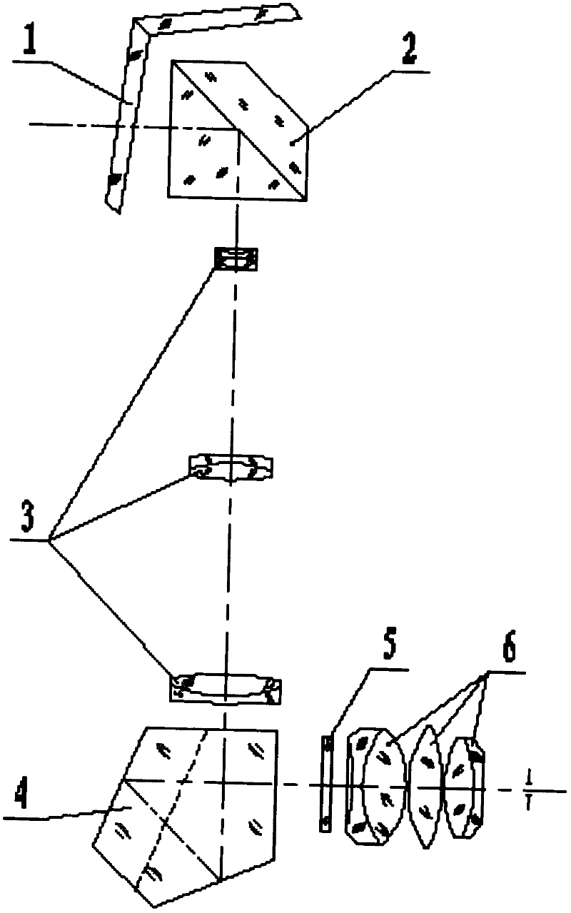
[0028] according to Figure 4 As shown, the preferred embodiment of the dynamic sighting device of the present invention consists of an electronic box 12, a display 14, a projection optical system, a warning light 17 and three cables 11, 13, 18. The electronic box 12, the display 14, and the projection optical system are all fixed inside the gunner's sight by corresponding brackets. The electronic box 12 is connected with the self-propelled antiaircraft artillery fire control computer through the first cable 11, and the electronic box 12 is connected with the display 14 through the second cable 13. Connection, the electronic box 12 is connected with the warning light 17 through the third cable 18.

[0029] according to Figure 5 As shown, the projection optical system includes a projection lens 15, a dichroic prism 16, and shares a...


PUM


Abstract

The invention discloses a dynamic sighting device for a gunner sighting lens of a self-propelled anti-aircraft gun and belongs to the technical field of gun observation and sighting. When a gunner emergently operates a gun, the dynamic sighting device is used for receiving target information or lead data sent by a fire control computer, resolving a coordinate value of an electron cursor in real time and generating a video signal which is controlled by a dynamic coordinate, and then a display is used for converting the video signal into a visible image and amplifying and projecting the visibleimage onto the partition plane of the gunner sighting lens by virtue of a projecting system, so that a dynamic electron cursor appears in the visual field of the gunner sighting lens. The dynamic sighting device is used for solving the technical problems that the reaction speed is low, the sighting precision is low and the lead error is big when the gunner emergently operates the gun by using a traditional sighting lens. The probability of grasping combat opportunity of the gunner is improved, the mental work intensity and spirit pressure of the gunner are relieved and the error rate of the gunner is also greatly reduced.

Description

technical field [0001] The invention belongs to the technical field of self-propelled artillery observation and aiming, and mainly relates to a dynamic sighting device, in particular to a dynamic sighting device for a self-propelled artillery gun sight. When working in this mode, a dynamic cursor can be used in the field of view of the gunner's sight of the antiaircraft gun to indicate the target information and the lead of the gun. Background technique [0002] The self-propelled anti-aircraft gun servo system is a system composed of a series of functional units, which accepts the command of the anti-aircraft gun fire control computer and makes the gun automatically complete the azimuth and pitch movements. With the advancement of technology, although the reliability of the servo system is constantly improving, there is still the possibility of failure due to its high complexity. Thereby many self-propelled anti-aircraft guns are equipped with an emergency auxiliary system...

Claims


Application Information

Patent Timeline
Patent Type & Authority Applications(China)
IPC IPC(8): F41G1/46
Inventor 李勤学何玉兰王涛柴继河闫丽陈秀萍张莹王刚
Owner CHINA NORTH IND NO 205 RES INST
Why Eureka
Try Eureka