Automatic cutting and sampling device for original soil sample preparation box and use method
A technology of automatic cutting and sampling device, applied in sampling device, measuring device, sampling and other directions, can solve problems such as low sample preparation efficiency
- Summary
- Abstract
- Description
- Claims
- Application Information
AI Technical Summary
Problems solved by technology
Method used
Image
Examples
specific Embodiment approach
[0036] It should be noted that the structures, proportions, sizes, etc. shown in this specification are only used to cooperate with the content disclosed in the specification for the understanding and reading of those familiar with this technology, and are not used to limit the conditions for the implementation of the present invention , any modification of structure, change of proportional relationship or adjustment of size shall still fall within the scope covered by the technical content disclosed in the present invention without affecting the effect and purpose of the present invention. .
[0037]At the same time, terms such as "upper", "lower", "left", "right", "middle" and "one" quoted in this specification are only for the convenience of description and are not used to limit the scope of this specification. The practicable scope of the invention and the change or adjustment of its relative relationship shall also be regarded as the practicable scope of the present inven...
Embodiment 1
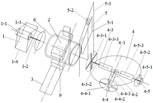
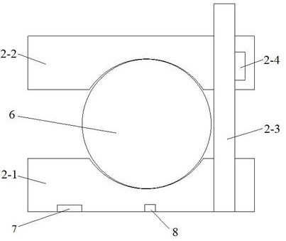
[0039] like figure 1 As shown, the present invention discloses an automatic cutting and sampling device for raw soil sample preparation box, including a push rod assembly 1, a clamping assembly 2, a transport rail 3, a sampling assembly 4, a cutting assembly 5 and a control assembly, the clamping assembly 2 Clamp the sample preparation box 6, the upper end surface of the transport guide rail 3 is provided with a toothed track, the lower end surface of the clamping assembly 2 is fixed with a gear motor 7, the gear motor 7 is matched with the toothed track, and the push rod assembly 1 is set on On one side of the width direction of the transport guide rail 3, the sampling assembly 4 is arranged on the other side of the width direction of the transport guide rail 3, and the cutting assembly 5 is arranged between the transport guide rail 3 and the sampling assembly 4, and the center of the push rod assembly 1 and the sampling assembly 4 On the same straight line, and the push rod ...
Embodiment 2
[0042] like figure 1 As shown, the preferred push rod assembly 1 includes a push rod motor 1-1, a push rod 1-2, a push rod disc 1-3 and a fixing seat 1-4, and the push rod motor 1-1 is fixed on the fixing seat 1- 4, the output end of the push rod motor 1-1 is connected to the push rod 1-2 through a gear converter, wherein the outer wall of the push rod 1-2 near the end of the push rod motor 1-1 is provided with threads, and the push rod 1-2 The other end is connected to the push rod disc 1-3, wherein the diameter of the push rod disc 1-3 is less than or equal to the diameter of the end face of the sample preparation box 6, the push rod motor 1-1, the push rod 1-2 and the push rod disc 1-3 The centers are on the same straight line, wherein the pusher disc 1-3 and the center of the end face of the sample preparation box 6 are on the same straight line and parallel to each other, and the pusher motor 1-1 is electrically connected to the control assembly.
[0043] A push rod posi...
PUM
| Property | Measurement | Unit |
|---|---|---|
| diameter | aaaaa | aaaaa |
Abstract
Description
Claims
Application Information
 - R&D
- Intellectual Property
- Life Sciences
- Materials
- Tech Scout
- Unparalleled Data Quality
- Higher Quality Content
- 60% Fewer Hallucinations
Browse by: Latest US Patents, China's latest patents, Technical Efficacy Thesaurus, Application Domain, Technology Topic, Popular Technical Reports.
© 2025 PatSnap. All rights reserved.Legal|Privacy policy|Modern Slavery Act Transparency Statement|Sitemap|About US| Contact US: help@patsnap.com


