Optical imaging camera lens
A technology of optical imaging lens and optical imaging system, which is applied in the direction of optics, optical components, instruments, etc., can solve the problems of large main ray exit angle, increased distortion, and long lens size, so as to improve imaging quality and reduce deflection angle , the effect of large field of view
- Summary
- Abstract
- Description
- Claims
- Application Information
AI Technical Summary
Problems solved by technology
Method used
Image

Examples
specific Embodiment 1
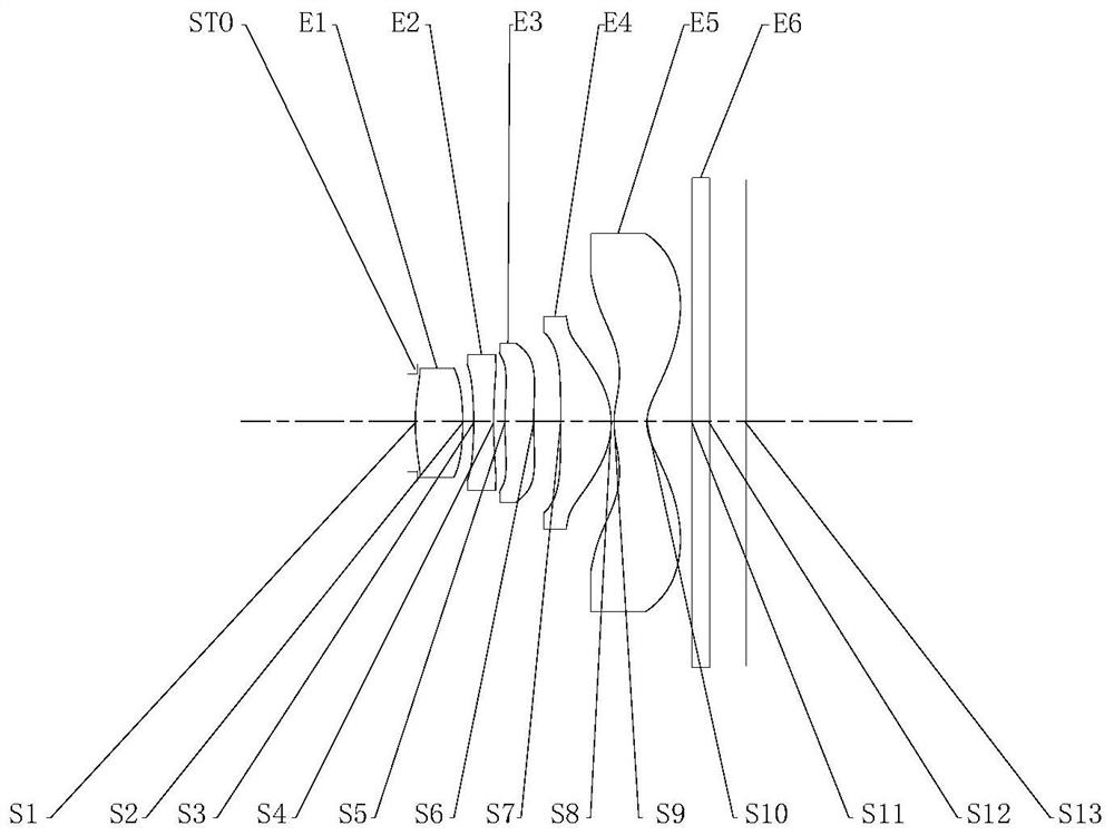
[0063] figure 1 It is a schematic diagram of the lens group structure of Embodiment 1 of the optical imaging lens of the present invention. The optical imaging lens includes in sequence from the object side to the image side along the optical axis: a diaphragm STO, a first lens E1, a second lens E2, a third lens E3, The fourth lens E4, the fifth lens E5, the filter E6 and the imaging surface S13.
[0064] The first lens E1 has positive refractive power, its object side S1 is convex, and its image side S2 is convex. The second lens E2 has negative refractive power, its object side S3 is concave, and its image side S4 is concave. The third lens E3 has positive refractive power, its object side S5 is convex, and its image side S6 is concave. The fourth lens E4 has positive refractive power, its object side S7 is concave, and its image side S8 is convex. The fifth lens E5 has negative refractive power, its object side S9 is convex, and its image side S10 is concave. The filter...
Embodiment 1
[0072] The optical imaging lens in embodiment 1 satisfies:
[0073] Semi-FOV=47.92°, wherein, Semi-FOV is half of the maximum field of view angle of the optical imaging system;
[0074] f1 / f4=1.47, wherein, f1 is the effective focal length of the first lens, and f4 is the effective focal length of the fourth lens;
[0075] f1 / fno=1.31, wherein, f1 is the effective focal length of the first lens, and fno is the relative F number of the lens;
[0076] TTL / ImgH=1.33, wherein, TTL is the on-axis distance from the object side of the first lens to the imaging surface, and ImgH is half of the diagonal length of the effective pixel area on the imaging surface;
[0077] |R2 / f|=1.33, wherein, R2 is the radius of curvature of the image side of the first lens, and f is the effective focal length of the optical imaging system;
[0078] (DT11+DT21) / TD=0.47, where DT11 is the maximum effective radius of the object side of the first lens, DT21 is the maximum effective radius of the object s...
specific Embodiment 2
[0094] image 3 It is a schematic diagram of the lens group structure of Embodiment 2 of the optical imaging lens of the present invention. The optical imaging lens includes in sequence from the object side to the image side along the optical axis: a stop STO, a first lens E1, a second lens E2, a third lens E3, The fourth lens E4, the fifth lens E5, the filter E6 and the imaging surface S13.
[0095] The first lens E1 has positive refractive power, its object side S1 is convex, and its image side S2 is concave. The second lens E2 has negative refractive power, its object side S3 is convex, and its image side S4 is concave. The third lens E3 has positive refractive power, its object side S5 is convex, and its image side S6 is concave. The fourth lens E4 has positive refractive power, its object side S7 is concave, and its image side S8 is convex. The fifth lens E5 has negative refractive power, its object side S9 is convex, and its image side S10 is concave. The filter E6 h...
PUM
 Abstract
Description
Claims
Application Information
 - R&D Engineer
- R&D Manager
- IP Professional
- Industry Leading Data Capabilities
- Powerful AI technology
- Patent DNA Extraction
Browse by: Latest US Patents, China's latest patents, Technical Efficacy Thesaurus, Application Domain, Technology Topic.
© 2024 PatSnap. All rights reserved.Legal|Privacy policy|Modern Slavery Act Transparency Statement|Sitemap