Battery charging circuit, battery pack and battery pack charging system

A battery charging and circuit technology, which is applied to battery disconnecting circuits, battery circuit devices, circuit devices, etc., can solve the problems of high cost and large volume, and achieve the effects of low cost, strong overcurrent capability and low heat generation.

Pending Publication Date: 2021-05-14
CHANGZHOU GLOBE
View PDF6 Cites 0 Cited by
  • Summary
  • Abstract
  • Description
  • Claims
  • Application Information

AI Technical Summary

Problems solved by technology

[0003] In view of the above-mentioned shortcomings of the prior art, the object of the present invention is to provide a battery charging circuit, a battery pack and a battery pack charging system, which are used to solve the need to add additional The cooling of the cooling device leads to technical problems of large size and high cost

Method used


Image

  • Battery charging circuit, battery pack and battery pack charging system
  • Battery charging circuit, battery pack and battery pack charging system
  • Battery charging circuit, battery pack and battery pack charging system

Examples


Embodiment 1

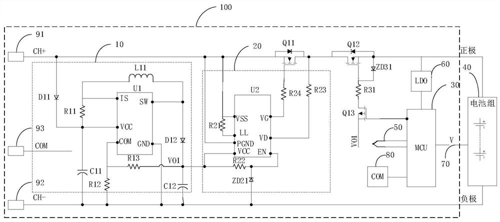
[0080]In this embodiment, iffigure 1 As shown, the battery charging circuit 100 is applied to a DC charging high side control, the power supply unit 10, is powered at a charge terminal, and the battery charging circuit 100 passes through the charging terminal andFigure 6 The output terminal of the DC charger 600 is connected, the NMOS tube Q11 is an NMOS tube having a body diode.

[0081]Specifically, such asfigure 1 As shown, the power supply unit 10 includes a boost circuit chip U1 (model, for example, MC34063), resistance R11, resistor R12, resistor R13, diode D11, diode D12, inductance L11, capacitor C11, and capacitance C12; the diode D11; The anode is connected to the source of the charging positive terminal 91 and the NMOS tube Q11, and the cathode of the diode D11 is connected to the charging negative terminal 92 via a capacitor C11, and the cathode of the diode D11 is respectively charged. The VCC pin of the circuit chip U1 and one end of the resistor R11 are connected, and th...

Embodiment 2

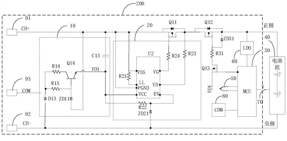
[0088]In this embodiment, iffigure 2 As shown, the battery charging circuit 200 is applied to AC charging high side control, the power supply unit 10 is powered at a charge terminal, and the battery charging circuit 200 is passed through the charging terminal andFigure 7 The output terminal of the AC charger 700 is connected, the NMOS tube Q11 is an NMOS tube having a body diode.

[0089]Specifically, such asfigure 2 As shown, the power supply unit 10 includes a resistor R14, a resistor R15, an NPN triode Q14, a capacitor C13, a diode D13, and a regulator diode ZD11; the base of the NPN triode is respectively composed to the cathode of the regulator diode ZD11, respectively. One end of the resistor R15 is connected, and the anode of the voltage regulator diode ZD 11 is connected to the source of the charging positive terminal 91 and the NMOS tube Q11, and the other end of the resistor R15 respectively corresponds to one end and the diode of the resistor R14, respectively. The cathode c...

Embodiment 3

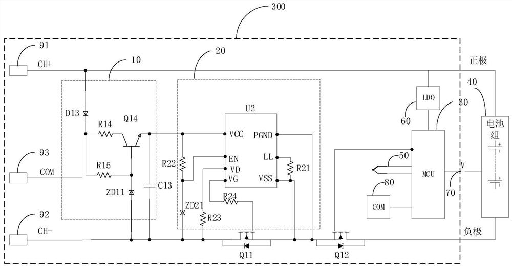
[0096]In this embodiment, ifimage 3 Design, the battery charging circuit 300 is suitable for a DC charging low-side control, the power supply unit 10 is powered at a charge terminal, and the battery charging circuit 300 passes through the charging terminal andFigure 6 The output terminal of the DC charger 600 is connected to the NMOS tube Q11 is an NMOS tube having a body diode.

[0097]Specifically, such asimage 3 As shown, the power supply unit 10 includes a resistor R14, a resistor R15, an NPN triode Q14, a capacitor C13, a diode D13, and a regulator diode ZD11; the base of the NPN triode is respectively composed to the cathode of the regulator diode ZD11, respectively. One end of the resistor R15 is connected, and the anode of the regulator diode ZD 11 is connected to the drain of the charging negative terminal 92 and the NMOS tube Q11, and the other end of the resistor R15 is respectively connected to one end and the diode D13 of the resistor R14, respectively. The cathode connect...


PUM


Abstract

The invention discloses a battery charging circuit, a battery pack and a battery pack charging system. The battery charging circuit comprises a first control switch, a switch control unit and a power supply unit, wherein the first control switch is arranged between a charging positive terminal and a positive electrode of the battery pack or between a charging negative terminal and a negative electrode of the battery pack, and the first control switch is an NMOS tube with a body diode; the switch control unit is connected with the grid electrode, the source electrode and the drain electrode of the first control switch, and the switch control unit controls the on-off of the first control switch by sampling the voltage of the source electrode and the drain electrode of the first control switch; and the output end of the power supply unit is connected with the power supply end of the switch control unit, and the power supply unit is used for supplying power to the switch control unit. The on-off state of the charging loop is controlled through the NMOS tube, and compared with existing PMOS tube control, the charging circuit is high in overcurrent capacity, small in heat emission, high in charging efficiency and capable of preventing a charging port from discharging.

Description

Technical field[0001]The present invention relates to the field of battery pack charging technologies, and more particularly to a battery charging circuit, a battery pack, and a battery pack charging system.Background technique[0002]At present, battery pack industries, battery pack charges generally achieve battery pack charging control through the MCU control of one or more PMOS tubes on the charging circuit, and in small current charging mode, this program is obvious, that is, it can prevent charging Pressing, but also guarantees no voltage when the charging port is idle, safe and reliable; but with the continuous innovation of battery technology, and the battery pack capacity is getting bigger and larger, large current fast charge technology is increasingly widely used; existing PMOS management program due to process Restrictions, the internal resistance is high in the fast charge mode, which requires an additional heat dissipation device to cool down, resulting in high volume an...

Claims


Application Information

Patent Timeline
IPC IPC(8): H02J7/00
CPCH02J7/0071H02J7/0029H02J7/0031H02J7/00032H02J2207/10Y02E60/10H02J7/007182H01L27/0255H01L27/0266H01L27/092
Inventor 李保安庄宪刘传君罗明
Owner CHANGZHOU GLOBE
Why Eureka
Try Eureka