

Release film dust removal device
A technology of dust removal device and release film, which is applied in the direction of separation method, separation of dispersed particles, use of liquid separation agent, etc., which can solve the problems of low dust removal efficiency and other problems
- Summary
- Abstract
- Description
- Claims
- Application Information
AI Technical Summary
Problems solved by technology
Method used
Image


Examples
Embodiment 1
[0035] Example 1, see Figure 1-9 :
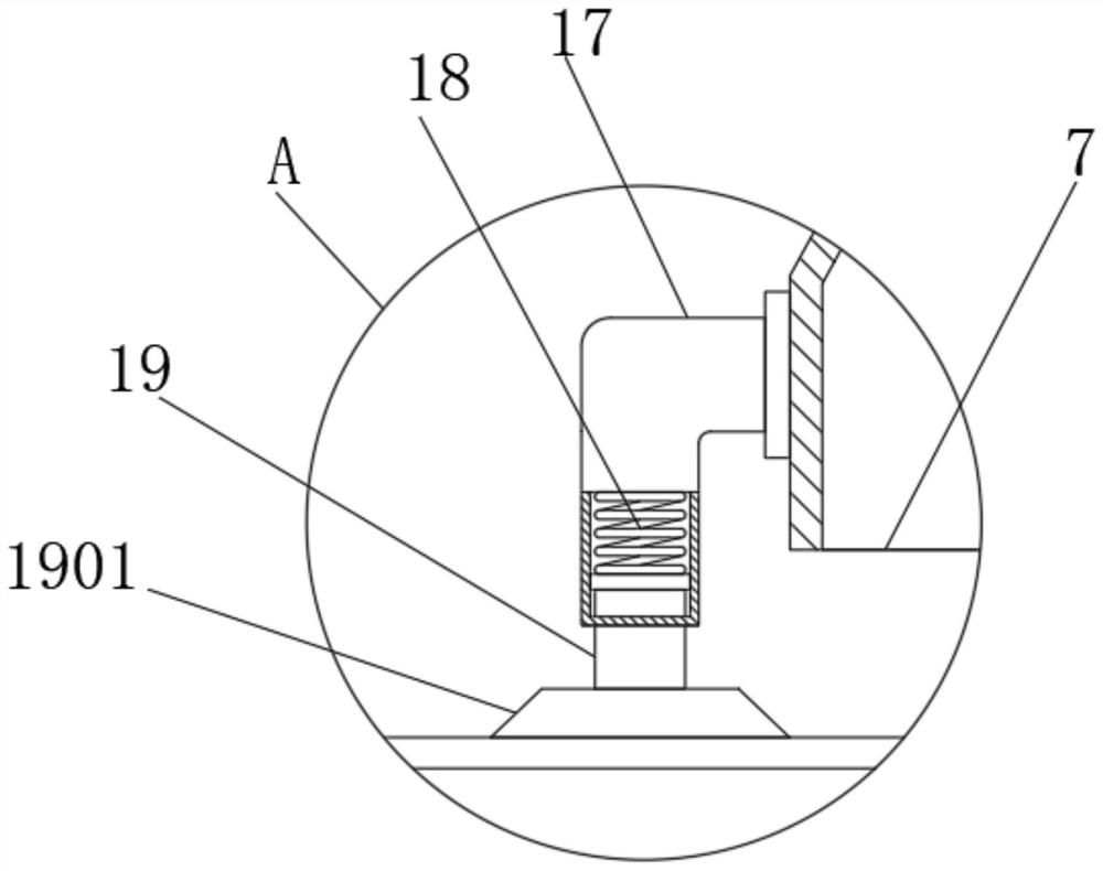
[0036] A dedusting device for a release film of the present invention comprises a fixed base plate 1, a release film 2 and a first motor 14, and the top of the fixed base plate 1 is fixedly connected with a left and right through door-shaped support frame 3, and the door-shaped support frame 3 A centrifugal exhaust fan 5 is installed on the top of the centrifugal exhaust fan 5, and the output port of the centrifugal exhaust fan 5 is connected with a dust suction pipe 6. The dust suction pipe 6 is bent and extends to the middle of the inner cavity of the door-shaped support frame 3 and is connected with a dust suction cover 7. The top of the dust cover 7 is fixedly connected to the top of the inner cavity of the door-shaped support frame 3 through two fixed columns 701, and the bottom of the dust suction pipe 6 penetrates into the inner cavity of the dust suction hood 7 and is fixedly connected with a shunt pipe 601, the shunt pipe The bot...
Embodiment 2
[0042] Example 2, see Figure 10-13 :
[0043] The inner cavity of the first mounting plate 4 and the second mounting plate 20 are all fixedly connected with bearings 24 at positions close to the middle, and the inner ring of each bearing 24 is fixedly connected with a clamping sleeve 25, and the inner ring of the clamping sleeve 25 The cavity is integrally formed with locking teeth, and the second motor 22 is installed on the back of the second mounting plate 20, and the power output shaft of the second motor 22 is fixedly connected with a locking column 23, and the locking column 23 passes through and is locked to the second mounting plate. The inner cavity of the clamping tube 25 on the board 20, one end of the winding tube 21 penetrates the inner cavity of the clamping tube 25 that is clamped to the second mounting plate 20, and the other end penetrates the cavity that is clamped to the first mounting plate 4. The inner cavity of the clamping tube 25; the bottom of the li...
Embodiment 3
[0044] Example 3, see figure 1 and Figure 9 :
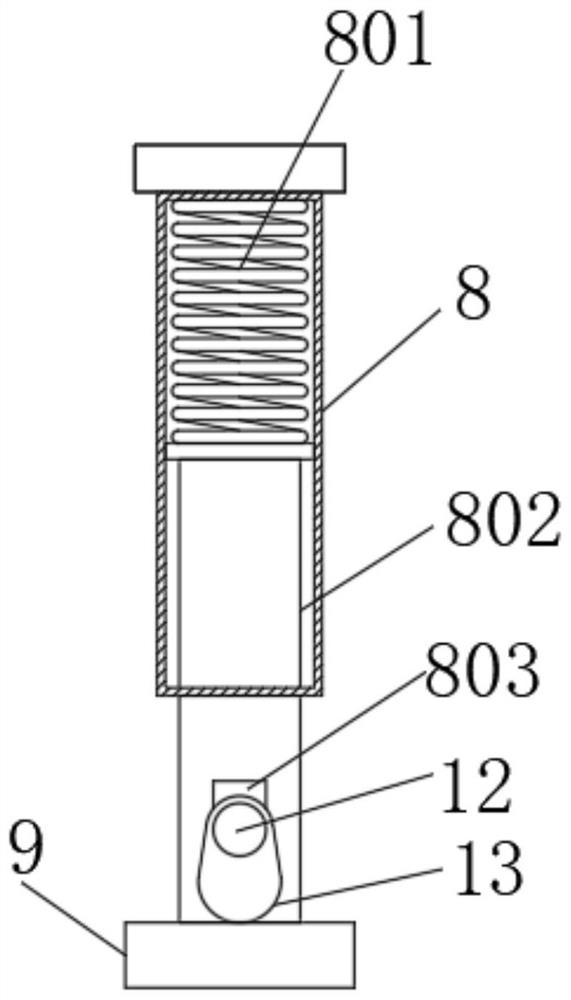
[0045] The right side of the door-shaped support frame 3 top is fixedly connected with a first dust collection box 10, and the bottom of the door-shaped support frame 3 inner cavity is fixedly connected with a second dust collection box 31, and the first dust collection box 10 and the second dust collection box 31 are all infused with liquid water in the inner cavity, and the output end of the centrifugal exhaust fan 5 is connected with a dust discharge pipe, which runs through and extends to the bottom of the inner cavity of the first dust collecting box 10, and the inner cavity of the door-shaped support frame 3 The bottom of the second dust collection box 31 is fixedly connected, and the top of the second dust collection box 31 is integrally formed with a funnel-shaped opening, which is located below the two vibrating plates 9, and the bottom of the release film 2 is close to The opening at the top of the second dust collec...
PUM
 Abstract
Description
Claims
Application Information