High-speed-driven injection molding machine mold closing structure

A driving mechanism and injection molding machine technology, applied in the field of injection molding machines, can solve problems such as high clamping force amplification ratio, fast linear motion speed, uncontrollable mold moving force, etc.

Inactive Publication Date: 2021-05-18
宁波瑞宝智能装备有限公司
View PDF1 Cites 2 Cited by
  • Summary
  • Abstract
  • Description
  • Claims
  • Application Information

AI Technical Summary

Problems solved by technology

[0002] At present, the mainstream all-electric injection molding machine mold opening and closing structure on the market adopts a five-point mechanical hinge structure. The mold moves in a straight line. The advantage of this structure is that the linear movement speed is fast and the clamping force amplification ratio is high. The disadvantage is that the clamping structure is driven by a servo motor. Once the electrical components fail, the torque provided by the servo motor will be amplified by the toggle. Several times of the fixed value, that is, the clamping force of the injection molding machine is several times of the set value, it is very easy to damage the mold, and it is difficult to guar

Method used


Image

  • High-speed-driven injection molding machine mold closing structure
  • High-speed-driven injection molding machine mold closing structure
  • High-speed-driven injection molding machine mold closing structure

Examples


Embodiment Construction

[0023] In order to further understand the content, features and effects of the present invention, the following examples are given, and detailed descriptions are given below with reference to the accompanying drawings.

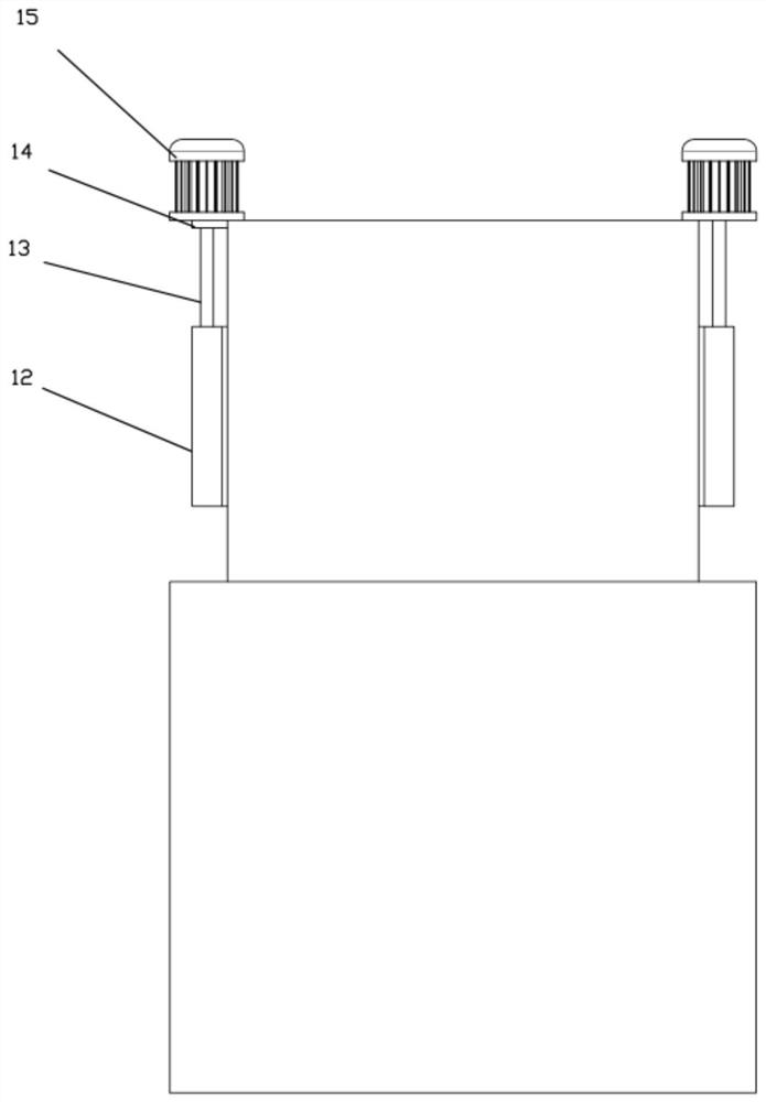
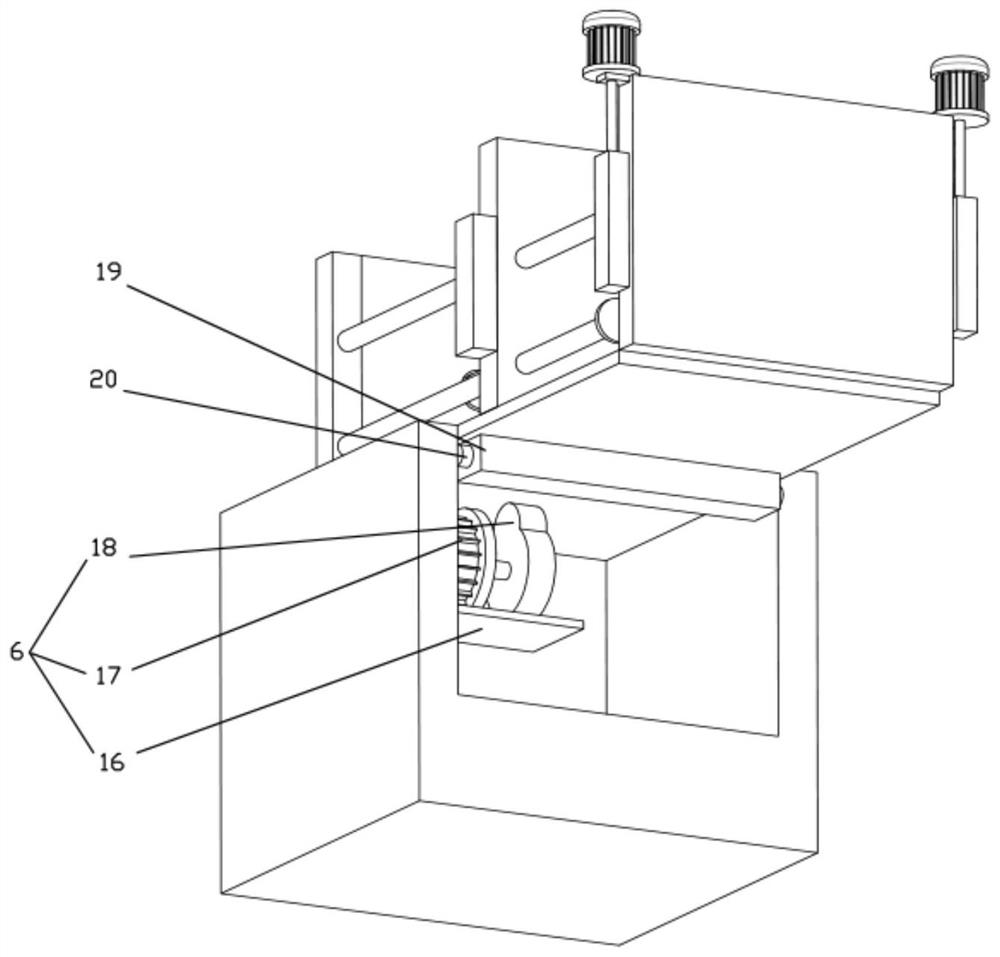
[0024] Please also refer to Figure 1 to Figure 3 , the mold clamping structure of the high-speed drive injection molding machine according to the embodiment of the present invention will be described in detail below in conjunction with the accompanying drawings.

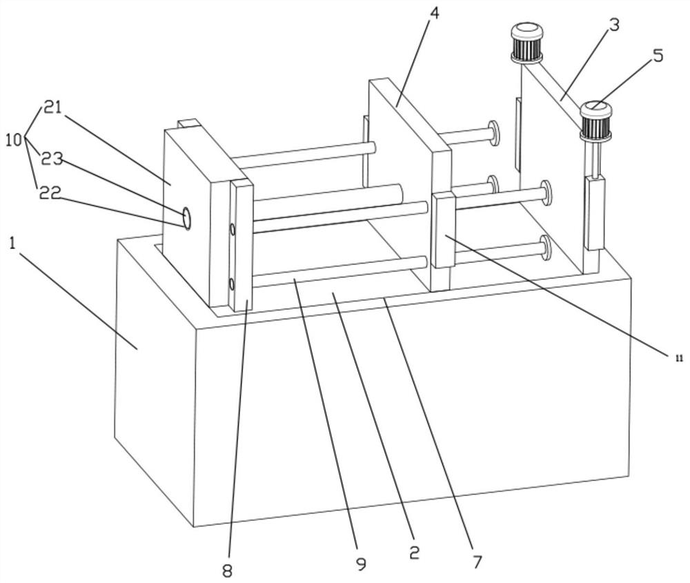
[0025] The high-speed driving injection molding machine mold clamping structure includes a base 1, a base plate 2, a fixed platen 3, a movable platen 4, an acceleration component 5, and an auxiliary separation component 6. A groove 7 is opened inside the base 1, and the groove 7 is close to the base 1. The surface is hingedly connected to the bottom plate 2, the upper end of the bottom plate 2 is fixed with a vertical rod 8, the inside of the vertical rod 8 is pierced with a guide rod 9, the movable...


PUM


Abstract

The invention discloses a high-speed-driven injection molding machine mold closing structure, and belongs to the technical field of injection molding machine. The high-speed-driven injection molding machine mold closing structure comprises a base, a bottom plate, a fixed mold plate, a movable mold plate, an acceleration assembly and an auxiliary separation assembly, a groove is formed in the base, the position, close to the surface of the base, of the groove is hinged to the bottom plate, a vertical rod is fixed to the upper end of the bottom plate, a guide rod penetrates through the vertical rod, the movable mold plate is slidably connected to the outside of the guide rod, the fixed mold plate is fixed to the upper end of the base, and a driving mechanism is fixed to the end, away from the fixed mold plate, of the movable mold plate. According to the structure, auxiliary acceleration of the injection molding machine mold closing structure is carried out through the magnetic attraction effect and mechanical rotation, mold closing can be rapidly carried out, losses of pressure, temperature and the like are reduced in the whole process of injecting melt into a cavity, then the balance is improved when the whole cavity is filled with the melt, and the product quality is improved.

Description

technical field [0001] The invention belongs to the technical field of injection molding machines, in particular to a mold clamping structure of a high-speed drive injection molding machine. Background technique [0002] At present, the mainstream all-electric injection molding machine mold opening and closing structure on the market adopts a five-point mechanical hinge structure. The mold moves in a straight line. The advantage of this structure is that the linear movement speed is fast and the clamping force amplification ratio is high. The disadvantage is that the clamping structure is driven by a servo motor. Once the electrical components fail, the torque provided by the servo motor will be amplified by the toggle. Several times of the fixed value, that is, the clamping force of the injection molding machine is several times of the set value, it is very easy to damage the mold, and the safety performance is difficult to be guaranteed. [0003] Chinese patent CN 10263...

Claims


Application Information

Patent Timeline
IPC IPC(8): B29C45/64B29C45/83
CPCB29C45/64B29C45/83B29C2045/645
Inventor 张旭东陈伟忠陈爱康
Owner 宁波瑞宝智能装备有限公司
Why Eureka
Try Eureka