Efficient oversleeve heat transfer printing device

A technology of thermal transfer printing and sleeve sleeves, which is applied to printing devices, transfer printing, rotary printing machines, etc., and can solve problems such as uneven printing fastness, pattern deformation, and non-detachable

Inactive Publication Date: 2021-05-18
江门市慈美科技有限公司
View PDF0 Cites 0 Cited by
  • Summary
  • Abstract
  • Description
  • Claims
  • Application Information

AI Technical Summary

Problems solved by technology

However, there are some technical difficulties that need to be overcome when heat transfer printing on these tubular fabrics: 1) Because the contact area is small, the pressure in the middle of the contact point is high, and the pressure on both sides of the pattern is small, so the transfer is easy to cause printing. 2) The carrier (such as sleeve, sleeve) supporting the fabric to be transferred is not installed firmly enough, causing the pattern after thermal transfer to be deformed, or even the outline of the pattern is blurred; 3) The carrier supporting the fabric to be transferred ( Such as sleeves and sleeves) are fixed installations and cannot be disassembled, which makes continuous production capacity weak and production efficiency low

Method used


Image

  • Efficient oversleeve heat transfer printing device
  • Efficient oversleeve heat transfer printing device
  • Efficient oversleeve heat transfer printing device

Examples


Embodiment Construction

[0022] In describing the present invention, it should be understood that the terms "center", "longitudinal", "transverse", "upper", "lower", "front", "rear", "left", "right", " The orientations or positional relationships indicated by "vertical", "horizontal", "top", "bottom", "inner" and "outer" are based on the orientations or positional relationships shown in the drawings, and are only for the convenience of describing the present invention and Simplified descriptions, rather than indicating or implying that the device or element referred to must have a particular orientation, be constructed and operate in a particular orientation, and thus should not be construed as limiting the invention. In the description of the present invention, unless otherwise specified, "plurality" means two or more.

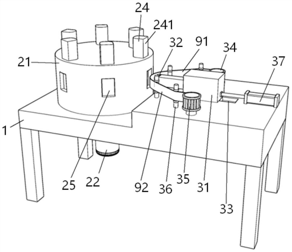
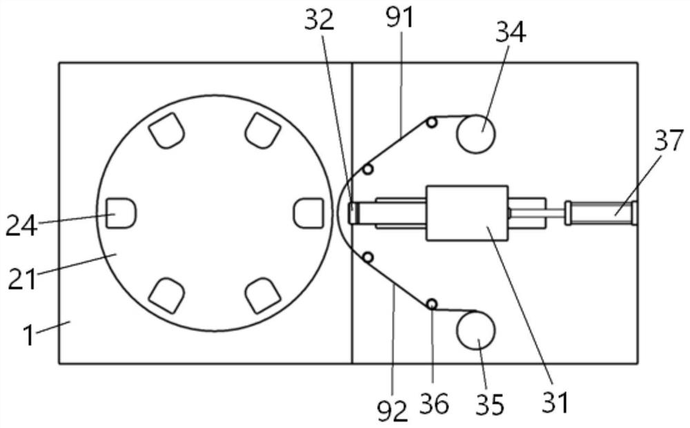
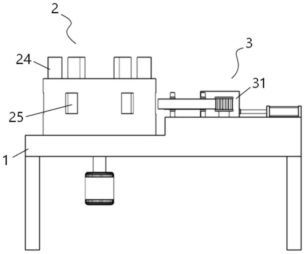
[0023] Please also see Figure 1 to Figure 4 , the high-efficiency sleeve heat transfer device of this case includes a machine 1, a preheating assembly 2 and a transfer assembly 3 a...


PUM


Abstract

The invention discloses an efficient oversleeve heat transfer printing device. The efficient oversleeve heat transfer printing device comprises a machine table, a preheating assembly and a transfer printing assembly, wherein the preheating assembly and the transfer printing assembly are arranged on the machine table; the preheating assembly comprises a rotary table arranged on the machine table and a servo motor arranged below the machine table, and an output shaft of the servo motor is connected with the rotary table; a plurality of mounting grooves are uniformly formed in the top of the rotary table in the circumferential direction of the rotary table, and oversleeve sleeves are detachably mounted in the mounting grooves; a plurality of transfer printing holes are transversely formed in the side wall of the rotary table, correspond to the mounting grooves and communicate with the corresponding mounting grooves; the transfer printing assembly comprises a transfer printing machine arranged on the machine table, and a high-temperature ironing head of the transfer printing machine faces the axis of the rotary table; a dovetail sliding block is arranged at the bottom of the transfer printing machine and matched with a dovetail sliding groove in the machine table; one side, opposite to the high-temperature ironing head, of the transfer printing machine is connected with an air cylinder; an unwinding frame, a winding frame and a plurality of guide frames are arranged on the two sides of the transfer printing machine correspondingly, and guide wheels are arranged on the guide frames. According to the efficient oversleeve heat transfer printing device, patterns can be continuously and efficiently transferred on the multiple oversleeves, and printed patterns are uniform in fastness.

Description

technical field [0001] The invention relates to the technical field of thermal transfer printing, in particular to an efficient sleeve thermal transfer device. Background technique [0002] Thermal transfer printing is a widely used printing technology. In this process, the pattern is pre-printed on the surface of the transfer film, and then the exquisite pattern on the transfer film is transferred by the heat transfer machine under the condition of maintaining a certain temperature and pressure. Printed on the surface of the product, the ink layer is integrated with the surface of the product after forming, which is realistic and beautiful, and greatly improves the grade of the product. Thermal transfer printing technology is widely used in fabric surface processing, such as using thermal transfer technology to transfer beautiful patterns on socks and sleeves to meet market demand. However, there are some technical difficulties to be overcome when heat transfer printing on...

Claims


Application Information

Patent Timeline
IPC IPC(8): B41F16/02
CPCB41F16/02B41P2217/60
Inventor 江俊葳
Owner 江门市慈美科技有限公司
Why Eureka
Try Eureka