Liquid crystal display device and method for manufacturing the same
- Summary
- Abstract
- Description
- Claims
- Application Information
AI Technical Summary
Benefits of technology
Problems solved by technology
Method used
Image
Examples
embodiment mode 1
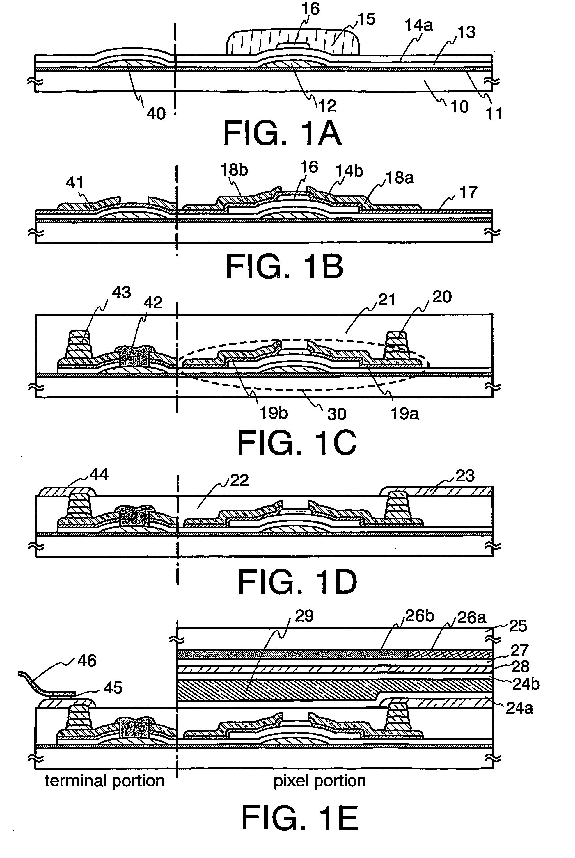
[0048] Here, a method for manufacturing an active matrix liquid crystal display device using an inverted staggered TFT as a switching element will be described. FIG. 1 shows a cross section of the manufacturing process.
[0049] First, a base film 11 for improving adhesion with a material layer to be later formed by a droplet discharge method is formed over a substrate 10. The base film 11 may be formed thin; accordingly, it can be regarded as base pretreatment. A photocatalyst (titanium oxide (TiO2), strontium titanate (SrTiO3), cadmium selenide (CdSe), potassium tantalate (KTaO3), cadmium sulfide (CdS), zirconium oxide (ZrO2), niobium oxide (Nb2O5), zinc oxide (ZnO), iron oxide (Fe2O3), tungsten oxide (WO3)) may be applied with a spray; alternatively, an organic material (polyimide, acryl, or a material having a skeletal structure including a bond of silicon (Si) and oxygen (O) which contains at least one of the group consisting of hydrogen, fluorine, alkyl group and aromatic hydroc...
embodiment mode 2
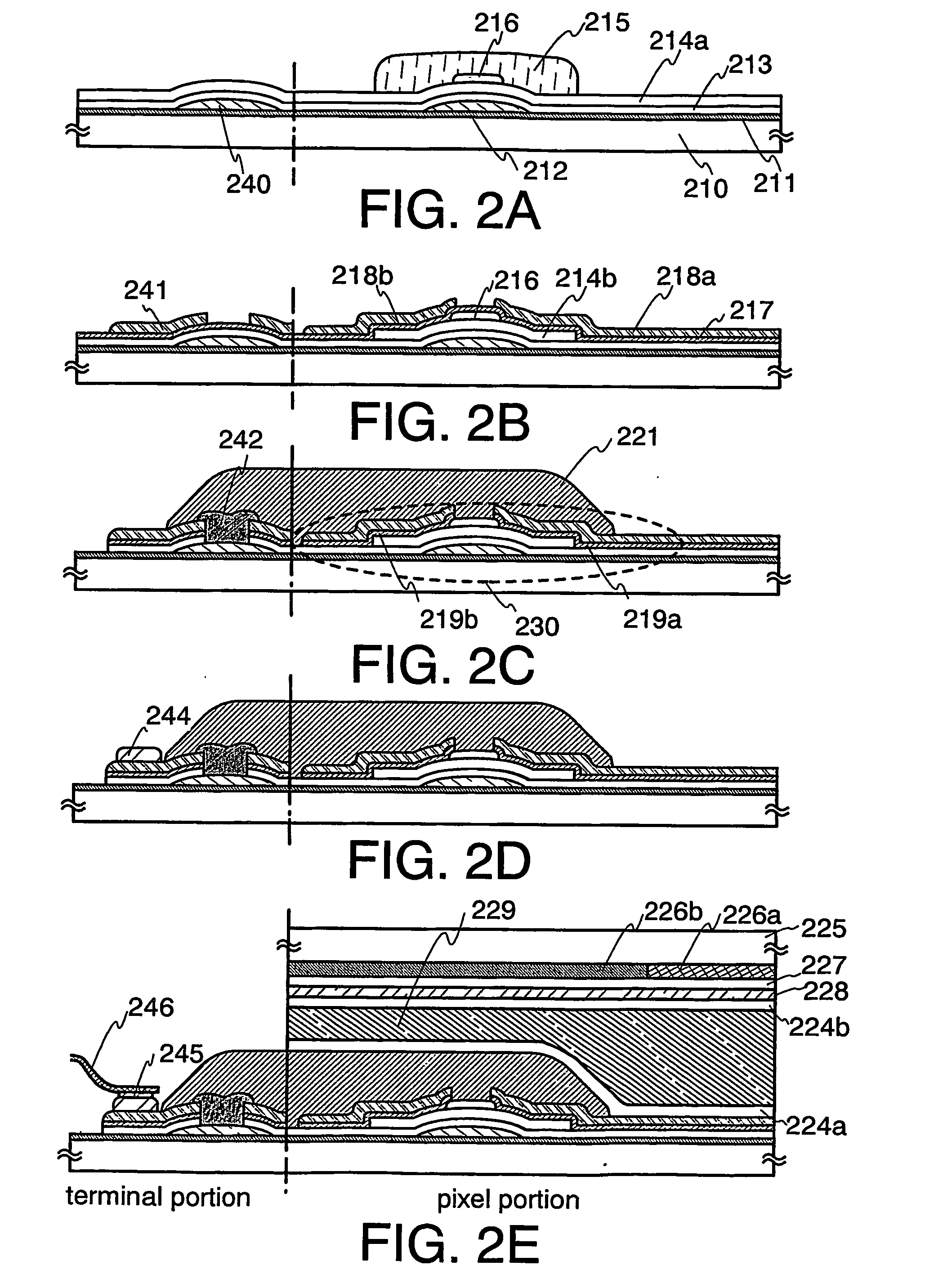
[0093] Here, an example in which the connection method is different from Embodiment Mode 1 will be shown. FIG. 2A to 2E show a cross section of manufacturing steps of an active matrix liquid crystal display device using an inverted staggered TFT as a switching element.
[0094] First, a state equivalent to FIG. 1A is made according to the steps shown in Embodiment Mode 1. A base film 211, a metal wiring 212, a wiring 240 extending to a terminal area are formed over a substrate 210. Further, a gate insulating film 213, a semiconductor film 214a, and an insulating layer 216 are sequentially formed thereover. A mask 215 covering the insulating layer 216 is formed by a droplet discharge method (FIG. 2A).
[0095] Next, a semiconductor film 214a except the area covered with the mask 215 is removed by dry etching or wet etching, so that a semiconductor layer 214b to be an active layer is formed.
[0096] After the mask 215 is removed, an n-type semiconductor film 217 is formed over the entire s...
embodiment mode 3
[0114] Here, an example in which the connection method is different from Embodiment Mode 1 will be shown. FIGS. 3A to 3D show a cross section of manufacturing steps of an active matrix liquid crystal display device using an inverted staggered TFT as a switching element.
[0115] First, a state equivalent to FIG. 1C is made according to the steps shown in Embodiment Mode 1. A base film 311, a metal wiring 312, a wiring 340 extending to a terminal area are formed over a substrate 310. Further, a gate insulating film 313, a semiconductor film, and an insulating layer 316 are sequentially formed thereover. A mask covering the insulating layer 316 is formed by a droplet discharge method. Next, a semiconductor film except the area covered with the mask is removed by dry etching or wet etching, so that a semiconductor layer 314 to be an active layer is formed. After the mask is removed, an n-type semiconductor film is formed over the entire surface. Next, a composition-containing a conductiv...
PUM
 Abstract
Description
Claims
Application Information
 - R&D
- Intellectual Property
- Life Sciences
- Materials
- Tech Scout
- Unparalleled Data Quality
- Higher Quality Content
- 60% Fewer Hallucinations
Browse by: Latest US Patents, China's latest patents, Technical Efficacy Thesaurus, Application Domain, Technology Topic, Popular Technical Reports.
© 2025 PatSnap. All rights reserved.Legal|Privacy policy|Modern Slavery Act Transparency Statement|Sitemap|About US| Contact US: help@patsnap.com


