Spinning ball removing device

A technology of walking bracket and roller, which is applied in the direction of textiles and papermaking, fabric surface trimming, etc., and can solve the problems of textile fabric damage, pilling again, and textile fabric off-line, etc.

Pending Publication Date: 2021-05-18
侯巧莉
View PDF10 Cites 2 Cited by
  • Summary
  • Abstract
  • Description
  • Claims
  • Application Information

AI Technical Summary

Problems solved by technology

[0006] Aiming at the deficiencies of the prior art, the present invention provides a textile depilling device, which solves the problem that traditional textile depilling equipment removes pilling by dragging, and it is easy to drag the textile fibers inside the fabric together duri

Method used


Image

  • Spinning ball removing device
  • Spinning ball removing device
  • Spinning ball removing device

Examples


Embodiment 1

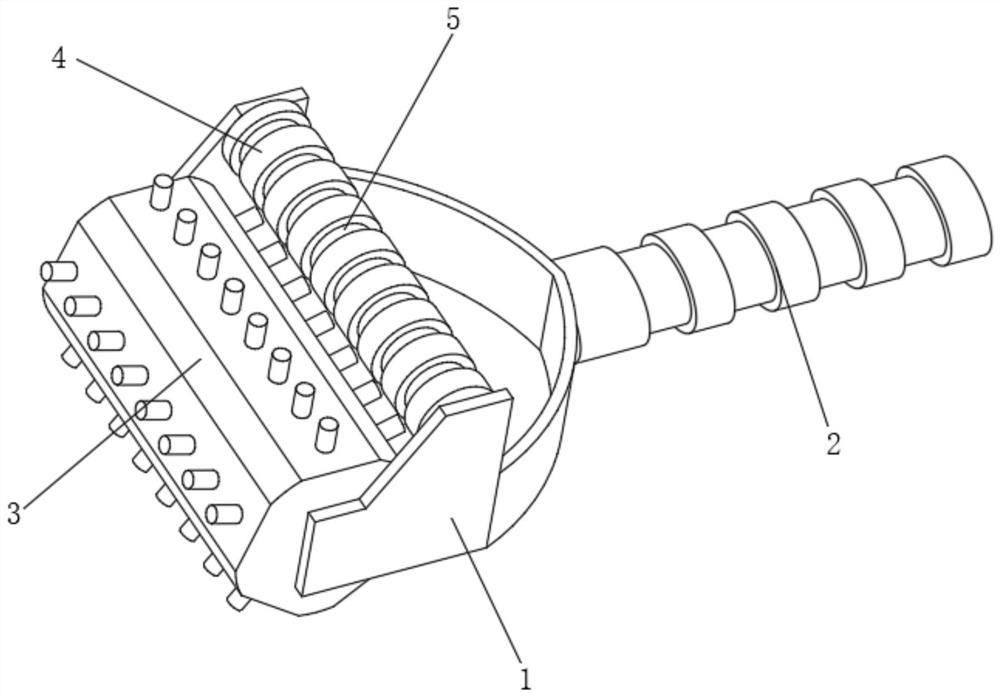
[0033] Such as Figure 1-2 As shown, the present invention provides a technical solution: a textile deballing device, including a walking frame 1, a drive handle 2 is fixedly connected to the middle position on the back of the walking frame 1, and a driving handle 2 is fixedly connected to the position near the front side of the walking frame 1. There is a contact stripping mechanism 3, and the walking bracket 1 is internally measured and is fixedly connected to the position above the back of the contact stripping mechanism 3. There is a cleaning sweep wheel 4, and the outer surface of the cleaning sweep wheel 4 is uniformly provided with scraping grooves 5;

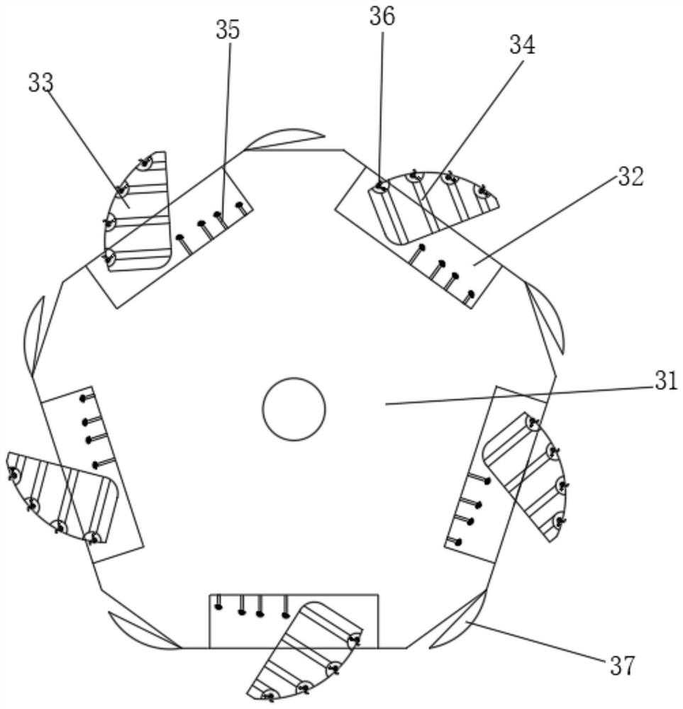
[0034]The contact and deballing mechanism 3 includes a walking roller 31, the two sides of the walking roller 31 are rotationally connected with the walking support 1, the outer surface of the walking roller 31 is evenly provided with a movable retaining groove 32, and one side of the movable retaining groove 32 is rotata...

Embodiment 2

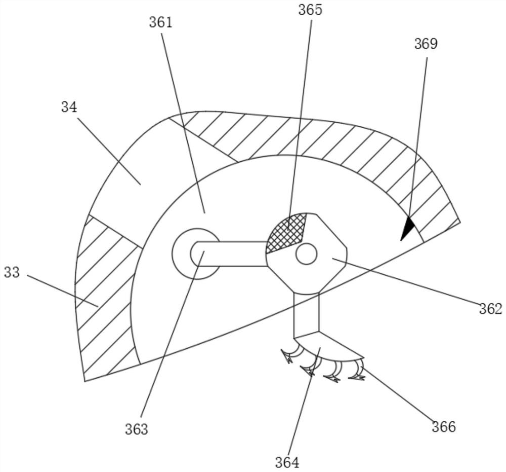
[0036] Such as Figure 3-4 As shown, on the basis of Embodiment 1, the present invention provides a technical solution: a textile deballing device, the contact scraper assembly 36 includes an adjustment circular groove 361, and the adjustment circular groove 361 is arranged on the contact drag reduction arc block 33 Inside, the adjusting circular groove 361 communicates with the conduction inner groove 34 , the inside of the adjusting circular groove 361 is rotatably connected with a transmission disk 362 , and the outer surface of the transmission disk 362 is fixedly connected with a drag reducing roller 363 .

[0037] The outer surface of the transmission disc 362 is fixedly connected with a fitting extrusion block 364, and the fitting extrusion block 364 is vertically arranged with the drag reducing roller 363. The outer surface of the transmission disc 362 is provided with a directional conductive groove 365, and the directional conductive groove 365 and the The conduction...

Embodiment 3

[0041] Such as Figure 5-6 As shown, on the basis of Embodiment 1 and Embodiment 2, the present invention provides a technical solution: a textile deballing device, the end cutting assembly 37 includes a support carrier 371, and the top of the support carrier 371 is in contact with the walking The roller 31 is fixedly connected, and the bottom of the support carrier 371 is fixedly connected with a lamination scraper 372 .

[0042] The surface of the front surface of the laminating scraper 372 is evenly provided with guiding and restricting conical grooves 373 , and the front of the support carrier 371 is evenly provided with surplus material storage grooves 374 , and the back of the guiding and restricting tapered grooves 373 communicates with the surplus material storage grooves 374 .

[0043] A cutting blade 375 is evenly and fixedly connected to both ends of the fitting scraper 372 , and a transmission guide wheel 376 is connected to the back of the fitting scraper 372 in r...


PUM


Abstract

The invention discloses a spinning ball removing device. The spinning ball removing device comprises a walking support; a driving grip is fixedly connected to the middle of the back face of the walking support; a contact ball removing mechanism is rotationally connected to the position, close to the front face, of the inner side of the walking support; a cleaning sweeping wheel is fixedly connected to the position, located above the back face of the contact ball removing mechanism, of the inner side of the walking support; and scraping grooves are evenly formed in the surface of the outer portion of the cleaning sweeping wheel. The invention relates to the technical field of spinning. According to the spinning ball removing device, the separation of spinning threads with fuzz balls is achieved, excessive dragging of the spinning threads with the fuzz balls is reduced, and the phenomenon of thread separation of spinning cloth is avoided.

Description

technical field [0001] The invention relates to the technical field of textiles, in particular to a textile deballing device. Background technique [0002] The original meaning of textile is taken from the general term of spinning and weaving, but with the continuous development and improvement of the textile knowledge system and subject system, especially after the emergence of non-woven textile materials and three-dimensional composite weaving technologies, it is not only the traditional hand spinning and weaving, also including non-woven technology. [0003] For example, the Chinese invention publication number is: a kind of dehairing machine for textile cloth of CN110616556B, which relates to the field of textile machinery. A torque motor, a pair of driving boxes is installed on the frame, and the depilatory roller and the dust suction nozzle are located between the pair of driving boxes. The shaft rod of the depilation roller is sleeved with a fixed ring near the driv...

Claims


Application Information

Patent Timeline
IPC IPC(8): D06C13/00
CPCD06C13/00
Inventor 侯巧莉
Owner 侯巧莉
Why Eureka
Try Eureka