
Double-shaft internally tangent type bidirectional transmission oil-gas multiphase pump

An oil and gas mixed pump and bidirectional transmission technology, applied in non-variable-capacity pumps, pumps, machines/engines, etc., can solve the problems of high vibration and noise, long axial length of mixed pump, and large volume of the pump body.

Pending Publication Date: 2021-05-18
LANZHOU UNIVERSITY OF TECHNOLOGY
View PDF6 Cites 0 Cited by
  • Summary
  • Abstract
  • Description
  • Claims
  • Application Information

AI Technical Summary

Problems solved by technology

[0002] At present, in the existing oil-gas mixed pump, a booster unit is composed of an impeller and a guide vane, and the whole pump body is composed of multiple booster units, so when working, the impeller rotates to do work, and the The guide vane is still and plays the role of drainage, so that the fluid enters the next-stage impeller with the minimum water loss. Therefore, the axial distance of the entire oil-gas mixed pump is very long. When it is necessary to increase the power of the mixed pump When this happens, it is necessary to increase the number of booster units, which will make the axial length of the mixed pump longer, resulting in large axial vibration and noise, unstable operation and other defects, and the existing oil-gas mixed pumps are An external motor is required to drive the impeller to rotate, making the volume of the pump body larger

Method used


Image

  • Double-shaft internally tangent type bidirectional transmission oil-gas multiphase pump
  • Double-shaft internally tangent type bidirectional transmission oil-gas multiphase pump
  • Double-shaft internally tangent type bidirectional transmission oil-gas multiphase pump

Examples


Embodiment Construction

[0014] The present invention will be described in detail below in conjunction with the accompanying drawings.

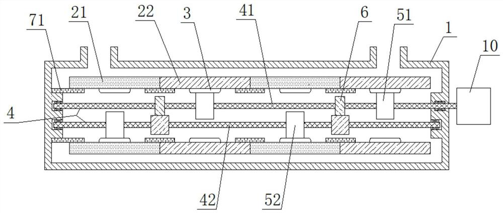
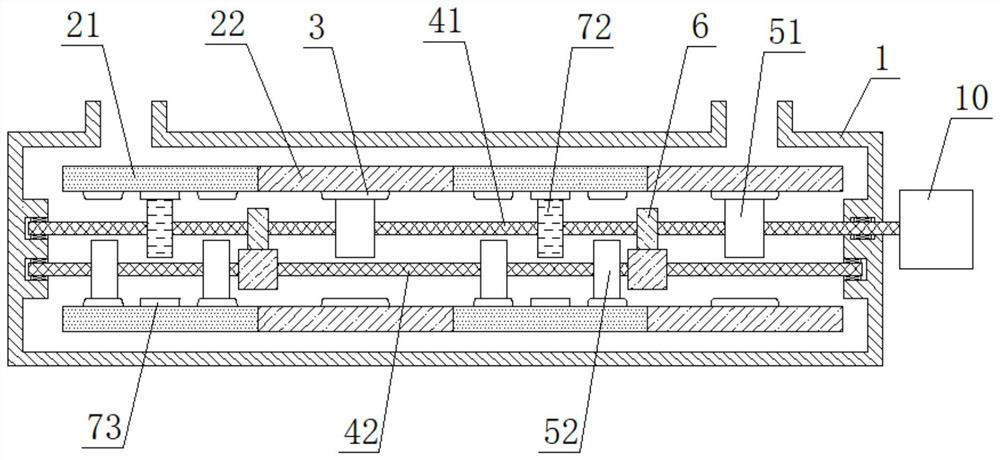
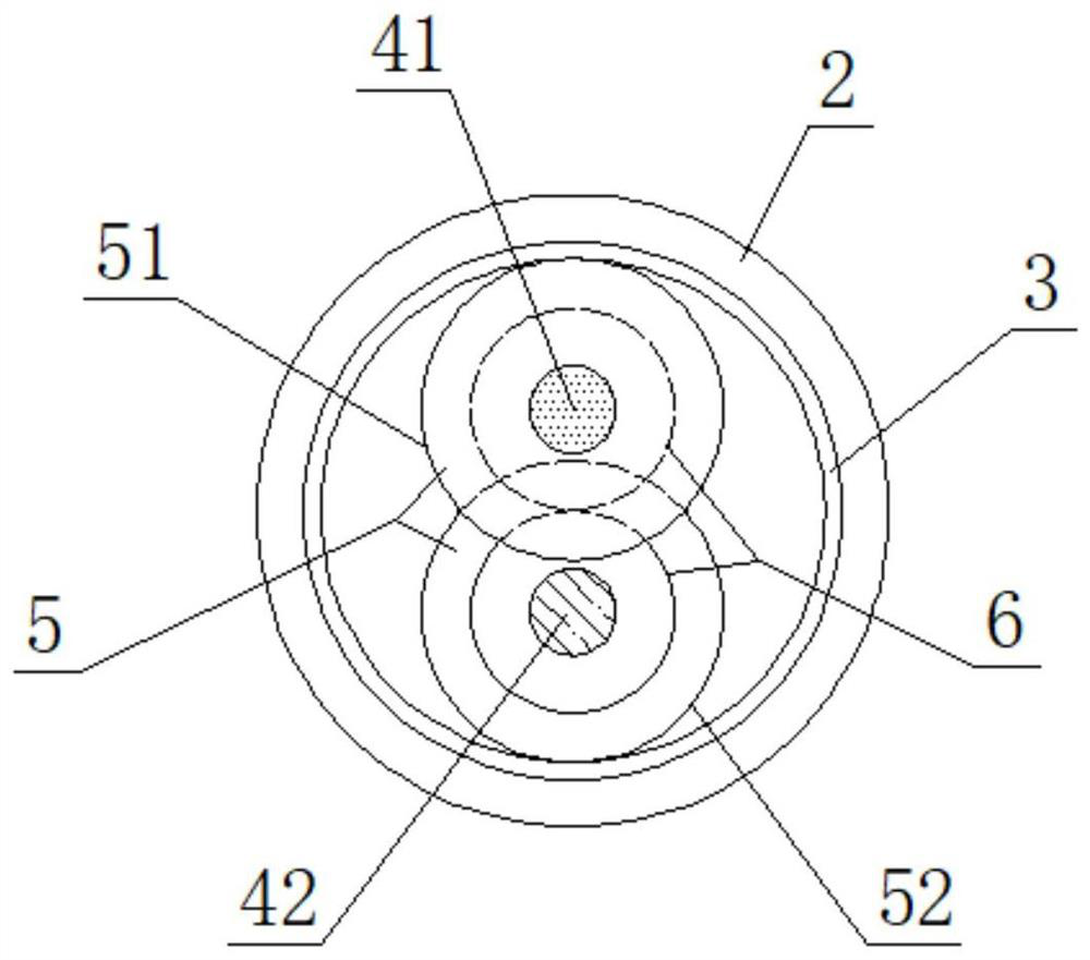
[0015] As shown in the figure, a dual-shaft inscribed two-way transmission oil-gas mixed transmission pump includes a pump body 1 and impellers 2 located in the pump body 1, wherein the impellers 2 include forward impellers 21 and reverse impellers arranged alternately. To the impeller 22, the blade inlet on the latter impeller 2 is designed with the blade outlet conditions on the previous impeller 2, a rack 3 is provided on the inner wall of the impeller 2, and upper and lower blades are arranged in the pump body 1. Two rotating shafts 4, one end of which one rotating shaft 4 is connected with motor 10, is provided with driving gear 5 and transmission gear 6 on described rotating shaft 4, wherein the lower driving gear 52 on the lower rotating shaft 42 is connected with the forward impeller 21 The rack 3 is inscribed and meshed, the upper driving gear 52 on the uppe...


PUM


Abstract

The invention discloses a double-shaft internally tangent type bidirectional transmission oil-gas multiphase pump which comprises a pump body and impellers. An upper rotating shaft and a lower rotating shaft are arranged in the pump body, wherein one end of one rotating shaft is connected with a motor, a driving gear and a transmission gear are arranged on each rotating shaft, wherein the lower driving gear on the lower rotating shaft is internally tangent and meshed with a rack in the forward impeller, the upper driving gear on the upper rotating shaft is internally tangent and meshed with a rack on the reverse impeller, the transmission gears on the two rotating shafts are meshed with each other, an original guide vane is replaced by the reverse impeller, at the moment, a supercharging unit is composed of one forward impeller and one reverse impeller, and after transmission of main transmission gears and the transmission gears, the rotating directions of the forward impeller and the reverse impeller are opposite to form a counter-rotating impeller set, so that when the multiphase pump works, the impellers in the forward direction and the reverse direction do work at the same time, the power of one existing supercharging unit is equivalent to the power of two traditional supercharging units, and the efficiency of the oil-gas multiphase pump is improved.

Description

technical field [0001] The invention relates to an oil-gas mixed delivery pump, in particular to an oil-gas mixed delivery pump with two-shaft inner-cut two-way transmission. Background technique [0002] At present, in the existing oil-gas mixed pump, a booster unit is composed of an impeller and a guide vane, and the whole pump body is composed of multiple booster units, so when working, the impeller rotates to do work, and the The guide vane is still and plays the role of drainage, so that the fluid enters the next-stage impeller with the minimum water loss. Therefore, the axial distance of the entire oil-gas mixed pump is very long. When it is necessary to increase the power of the mixed pump When this happens, it is necessary to increase the number of booster units, which will make the axial length of the mixed pump longer, resulting in large axial vibration and noise, unstable operation and other defects, and the existing oil-gas mixed pumps are An external motor is n...

Claims


Application Information

Patent Timeline
Patent Type & Authority Applications(China)
IPC IPC(8): F04D31/00
CPCF04D31/00
Inventor 权辉杜媛英杨亚威尚冬梅杨雪玲兰剑英孙晨曦刘晓艺
Owner LANZHOU UNIVERSITY OF TECHNOLOGY
Learn More