
Installation and adjustment method of optical imaging system

A technology of optical imaging system and assembly method, which is applied in optics, optical components, instruments, etc., and can solve problems such as high equipment cost, complicated operation, and poor imaging quality

Active Publication Date: 2021-05-18
常州奥创医疗科技有限公司
View PDF3 Cites 3 Cited by
  • Summary
  • Abstract
  • Description
  • Claims
  • Application Information

AI Technical Summary

Problems solved by technology

If you only rely on the outer circle of the lens as a reference for adjustment, although the operation is simple, the accuracy is low and the image quality is poor
The centering instrument can measure the center of curvature of the upper and lower surfaces of the lens, and then calculate the optical axis deviation of the lens by software, and then adjust the position. Although the centering instrument has high precision and can improve the accuracy of assembly and adjustment, the operation is complicated and the equipment cost is high.

Method used


Image

  • Installation and adjustment method of optical imaging system
  • Installation and adjustment method of optical imaging system
  • Installation and adjustment method of optical imaging system

Examples


Embodiment Construction

[0030] In order to make the content of the present invention more clearly understood, the present invention will be further described in detail below based on specific embodiments and in conjunction with the accompanying drawings.

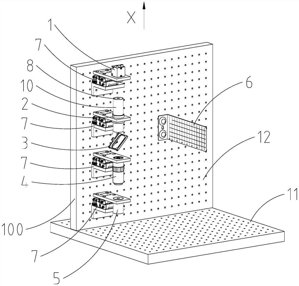
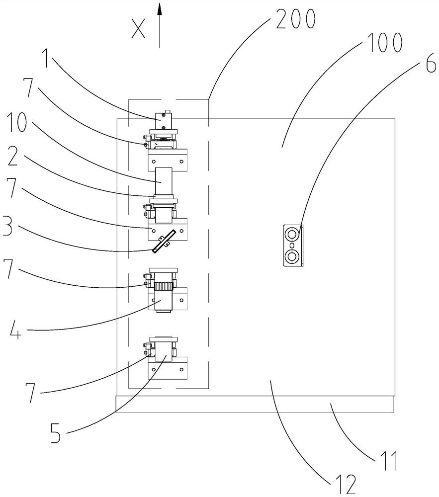
[0031] Such as figure 1 , 2 As shown, a method for installing and adjusting an optical imaging system, the optical imaging system includes a mount 100 and at least one optical imaging device 200, the optical imaging device 200 includes a camera 1, a lens tube lens 2, a beam splitter 3 and an objective lens 4, This method completes the installation and adjustment of the optical imaging device 200 based on the light source device 5 and the collimating screen 6, and the steps of the method include:

[0032] S1: Install the camera 1 and the light source device 5 on the mount 100, adjust the position and angle of the light source device 5 and adjust the position and angle of the camera 1, so that the light source device 5 Emit the light spot along the...


PUM


Abstract

The invention discloses an installation and adjustment method of an optical imaging system. The optical imaging system comprises a mounting seat and an optical imaging device, the optical imaging device comprises a camera, a lens cone lens, a spectroscope and an objective lens. The method is used to complete the installation and adjustment of the optical imaging device based on a light source device and a collimating screen. The method comprises the steps of S1, adjusting the position and the angle of the light source device and the position and the angle of the camera so that the light source device emits light spots in the X direction and the emitted light spots vertically enter the camera for imaging, and the light spots have linear parts; and S2, installing the lens cone lens on the mounting seat, enabling the light spots emitted by the light source device to penetrate through the lens cone lens and then enter the camera for imaging, and adjusting the position and the angle of the lens cone lens so that the positions of the light spots in the camera can coincide with a first reference position. According to the invention, the adjustment precision can be improved, the operation is simple and fast, an adjustment speed can be improved, and the implementation cost is reduced.

Description

technical field [0001] The invention relates to a method for assembling and adjusting an optical imaging system. Background technique [0002] At present, the position accuracy and coaxiality of each component in the optical imaging system directly determine the imaging quality of the optical imaging system. Due to the functional integration of the optical imaging system, the number of internal lenses is increasing, and the difficulty of assembly and adjustment is getting higher and higher. If only relying on the outer circle of the lens for adjustment, although the operation is simple, the accuracy is low and the image quality is poor. The centering instrument can measure the center of curvature of the upper and lower surfaces of the lens, and then calculate the optical axis deviation of the lens by software, and then adjust the position. Although the centering instrument has high precision and can improve the accuracy of assembly and adjustment, the operation is complicat...

Claims


Application Information

Patent Timeline
IPC IPC(8): G02B27/62
CPCG02B27/62
Inventor 徐特刘建明
Owner 常州奥创医疗科技有限公司
Learn More