Wiring device of circuit breaker

A wiring device and circuit breaker technology, which is applied to circuit breaker components, emergency protection devices, circuits, etc., can solve the problems of temperature rise and high cost

Active Publication Date: 2021-05-18
ZHEJIANG SHILONG ELECTRICAL TECH CO LTD
View PDF4 Cites 2 Cited by
  • Summary
  • Abstract
  • Description
  • Claims
  • Application Information

AI Technical Summary

Problems solved by technology

[0003] Therefore, the technical problem to be solved by the present invention is to overcome the defects of temperature rise and high cost in the circuit breaker wiring device in the prior art, thereby providing a circuit breaker connection device with low temperature rise and low cost

Method used


Image

  • Wiring device of circuit breaker
  • Wiring device of circuit breaker
  • Wiring device of circuit breaker

Examples


Embodiment

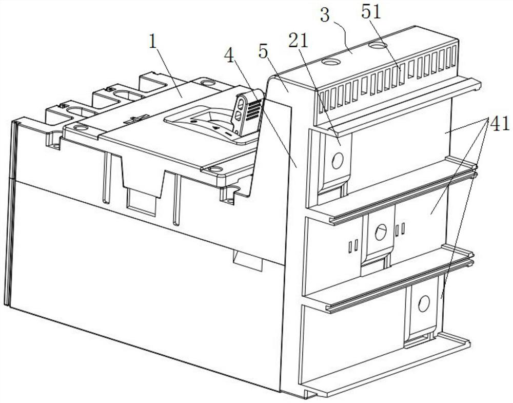
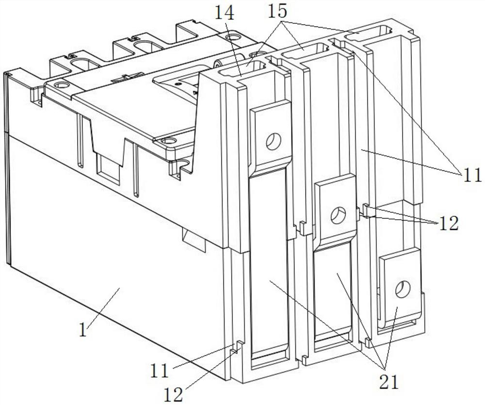
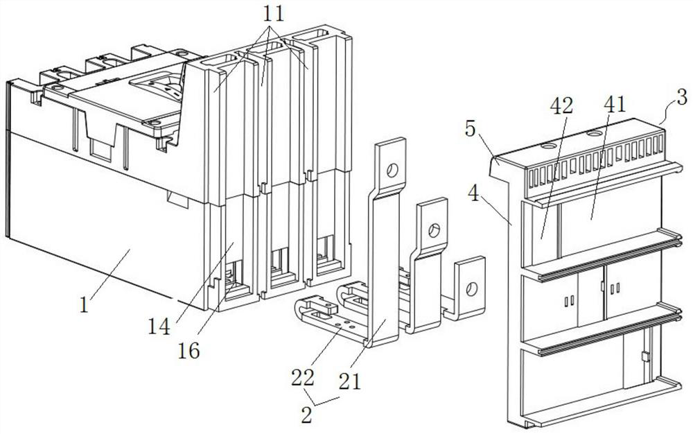
[0038] This embodiment provides a wiring device for a circuit breaker, such as figure 1 As shown, it includes a circuit breaker body 1 , a conductive connector 2 and a wiring cover 3 .

[0039] Circuit breaker body 1, such as Figure 7As shown, there is an arc extinguishing system 13, and a baffle 14 arranged on the rear side of the arc extinguishing system 13, and an air passage extending vertically upward is provided between the arc extinguishing system 13 and the baffle 14 15, the top of the air passage 15 is set higher than the highest point of the rotation track of the operating handle 10 of the circuit breaker body 1 . The outer surface of the baffle plate 14 has second slots 11 disposed on both sides in the width direction of the first connecting plate 21 , and two second stoppers 12 are provided at both ends of the opening of the second slot 11 .

[0040] There are three conductive connectors 2, which are arranged on the wiring side of the circuit breaker body 1 and...


PUM


Abstract

The invention provides a wiring device of a circuit breaker. The wiring device comprises: a circuit breaker body; a plurality of conductive connecting pieces arranged on the wiring side of the circuit breaker body, wherein each conductive connecting piece is provided with a first connecting plate which is arranged along the vertical direction and is exposed outside the circuit breaker body, and a second connecting plate which is inserted into the circuit breaker body; and a wiring cover cap which is detachably mounted on the circuit breaker body and is suitable for shielding the second connecting plate and part of the first connecting plate, wherein the wiring cover cap is provided with a plurality of first slots which are arranged at intervals along the height direction of the wiring cover cap and are used for the insertion of the corresponding conductive busbars, and open holes through which the other part of the first connecting plate extends to the first slots. When the wiring device is assembled, the second connecting plates of the plurality of conductive connecting pieces are inserted into the circuit breaker body, then the wiring cover is installed on the circuit breaker body, and finally the plurality of conductive busbars are correspondingly inserted into the first slots in one side of the wiring cover to be connected with the first connecting plates, so that the wiring device has the advantages of being simple in structure and quick and convenient to disassemble and assemble.

Description

technical field [0001] The invention relates to the technical field of connection devices for power distribution appliances, in particular to a connection device for a circuit breaker. Background technique [0002] When an existing circuit breaker is connected to a power supply, it generally adopts a copper bar connection or a bus bar connection. When copper bars are used for connection, such as Figure 8 As shown, the copper bar has a first copper bar 01 that can be connected to the circuit breaker terminal, and a second copper bar 02 vertically connected to the first copper bar 01, and the junction of the first copper bar 01 and the second copper bar 02 It needs to be drilled and connected by screws, which increases the temperature rise. In addition, due to the need to consider the creepage distance between copper bars of different phases, it not only increases the amount of copper bars, increases the cost, but also increases the temperature rise; When connecting with bus...

Claims


Application Information

Patent Timeline
Patent Type & Authority Applications(China)
IPC IPC(8): H01H71/08H01H73/06H01H73/18H01H73/20H01H9/52H01H71/02
CPCH01H71/08H01H71/02H01H73/18H01H73/06H01H73/20H01H9/52
Inventor 朱型沦冯伟通崔争艳徐晓初苏林杰苏海军
Owner ZHEJIANG SHILONG ELECTRICAL TECH CO LTD
Why Eureka
Try Eureka