Short-circuit current providing method and system of grid-connected converter

A short-circuit current and converter technology, which is used in AC network circuits, AC network voltage regulation, photovoltaic power generation, etc.

Active Publication Date: 2021-05-18
SHANGHAI JIAO TONG UNIV
View PDF5 Cites 4 Cited by
  • Summary
  • Abstract
  • Description
  • Claims
  • Application Information

AI Technical Summary

Problems solved by technology

During the grid short-circuit fault, the general practice is to determine the active and reactive power injected by the converter into the grid according to the grid voltage drop during the grid fault. This control method is not the optimal use of the converter's over-current capacity

Method used


Image

  • Short-circuit current providing method and system of grid-connected converter
  • Short-circuit current providing method and system of grid-connected converter
  • Short-circuit current providing method and system of grid-connected converter

Examples


Embodiment 1

[0058] A method for providing a short-circuit current of a grid-connected converter according to the present invention includes:

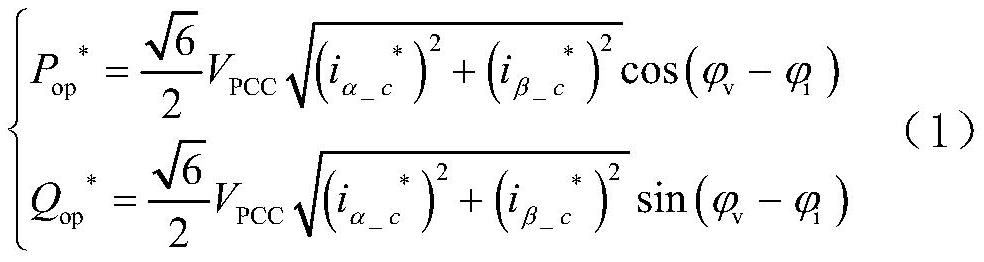
[0059] Step S1: When a short circuit occurs in the power grid, the reference power during the converter failure period is calculated through the power command setting;

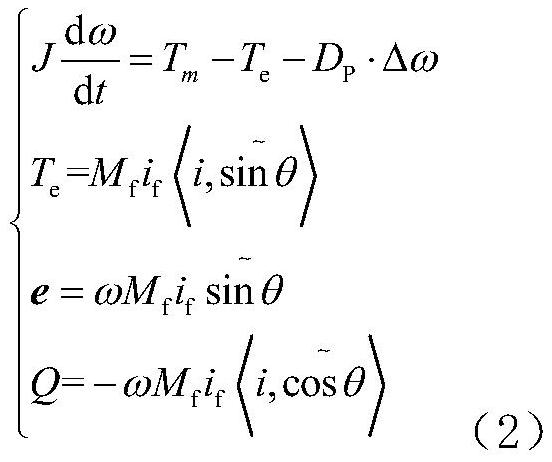
[0060] Step S2: Based on the reference power during the fault period of the converter, the virtual electromotive force is calculated through the self-synchronous voltage source control strategy;

[0061] Step S3: Based on the virtual electromotive force and virtual electronic impedance calculated by the self-synchronous voltage source control strategy, the current reference value in the two-phase stationary coordinate system is obtained, and the converter reference voltage signal is obtained through the current control inner loop and the grid voltage feedforward control , the converter modulation signal is obtained through the modulation link;

[0062] Step S4: Control the output ...

Embodiment 2

[0107] Embodiment 2 is a modification of embodiment 1

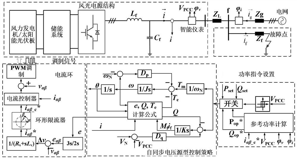
[0108] According to the present invention, a method for providing short-circuit current of a grid-connected converter is provided. The whole control method is composed of three parts: 1) self-synchronous voltage source control strategy; 2) current-limiting control of the converter under grid failure; 3) conversion optimal short-circuit current control.

[0109] refer to figure 1 , which provides a method control block diagram for a short-circuit current of a grid-connected converter in an embodiment of the present invention. Wind power is composed of wind turbines / solar photovoltaic panels, energy storage systems, grid-connected converters, etc., L f and C f It is the inductance and capacitance filter on the AC side of the converter. i is the grid-connected current of the converter, V pcc is the effective value of the grid-connected point voltage, Z L and Z g are the line impedance and grid impedance based on Theve...


PUM


Abstract

The invention provides a short-circuit current providing method and system for a grid-connected converter, and the method comprises the steps: M1, when a power grid is short-circuited, setting and calculating a reference power during a fault period of the converter through a power instruction; M2, on the basis of the reference power during the converter fault period, calculating a virtual electromotive force through a self-synchronizing voltage source type control strategy; M3, obtaining a current reference value under the two-phase static coordinate system through calculation based on the virtual electromotive force and the virtual electronic impedance obtained through calculation of the self-synchronizing voltage source type control strategy, obtaining a converter reference voltage signal through a current control inner ring and power grid voltage feedforward control, and obtaining a converter modulation signal through a modulation link; and M4, controlling the output voltage of the converter according to the converter modulation signal, and further controlling the short-circuit current of the grid-connected converter during the power grid fault period. According to the invention, a current loop is embedded in a voltage source type control strategy, and the control strategy does not need to be switched before and after a system fault.

Description

technical field [0001] The present invention relates to the technical field of electrical automation equipment, in particular to a short-circuit current supply method and system for a grid-connected converter. Background technique [0002] With the rapid development of wind power, a large number of traditional synchronous generators in the grid have been replaced. Wind and wind power is generally connected to the grid through a power electronic converter. The traditional current source control method of the grid-connected converter makes the wind and wind power present a current source characteristic, which cannot provide inertia and damping support for the grid like a traditional synchronous generator. The penetration grid presents the characteristics of low inertia and low damping, and the stability of the power system and the reliability of power supply are greatly challenged. The voltage source control can control the power electronic converter to have the dynamic chara...

Claims


Application Information

Patent Timeline
Patent Type & Authority Applications(China)
IPC IPC(8): H02J3/00H02J3/12H02J3/38
CPCH02J3/001H02J3/12H02J3/381H02J2300/24H02J2300/28Y02E10/56Y02E10/76
Inventor 蔡旭刘畅李睿
Owner SHANGHAI JIAO TONG UNIV
Why Eureka
Try Eureka