Deep-sea video shooting and wireless transmission integrated system

A technology of video shooting and wireless transmission, which is applied in closed-circuit television systems, components of TV systems, TVs, etc., and can solve problems such as unfavorable equipment maintenance and poor real-time video transmission in time-sharing work.

Active Publication Date: 2021-05-18
XIDIAN UNIV
View PDF12 Cites 0 Cited by
  • Summary
  • Abstract
  • Description
  • Claims
  • Application Information

AI Technical Summary

Problems solved by technology

Although this method can realize video shooting and wireless optical communication functions, the real-time performance of video transmission is poor due to time-sharing work; and the auxiliary lights and wireless optical communication equipment are frequently turned on and off, which is not conducive to the maintenance of equipment.

Method used


Image

  • Deep-sea video shooting and wireless transmission integrated system
  • Deep-sea video shooting and wireless transmission integrated system
  • Deep-sea video shooting and wireless transmission integrated system

Examples


Embodiment 1

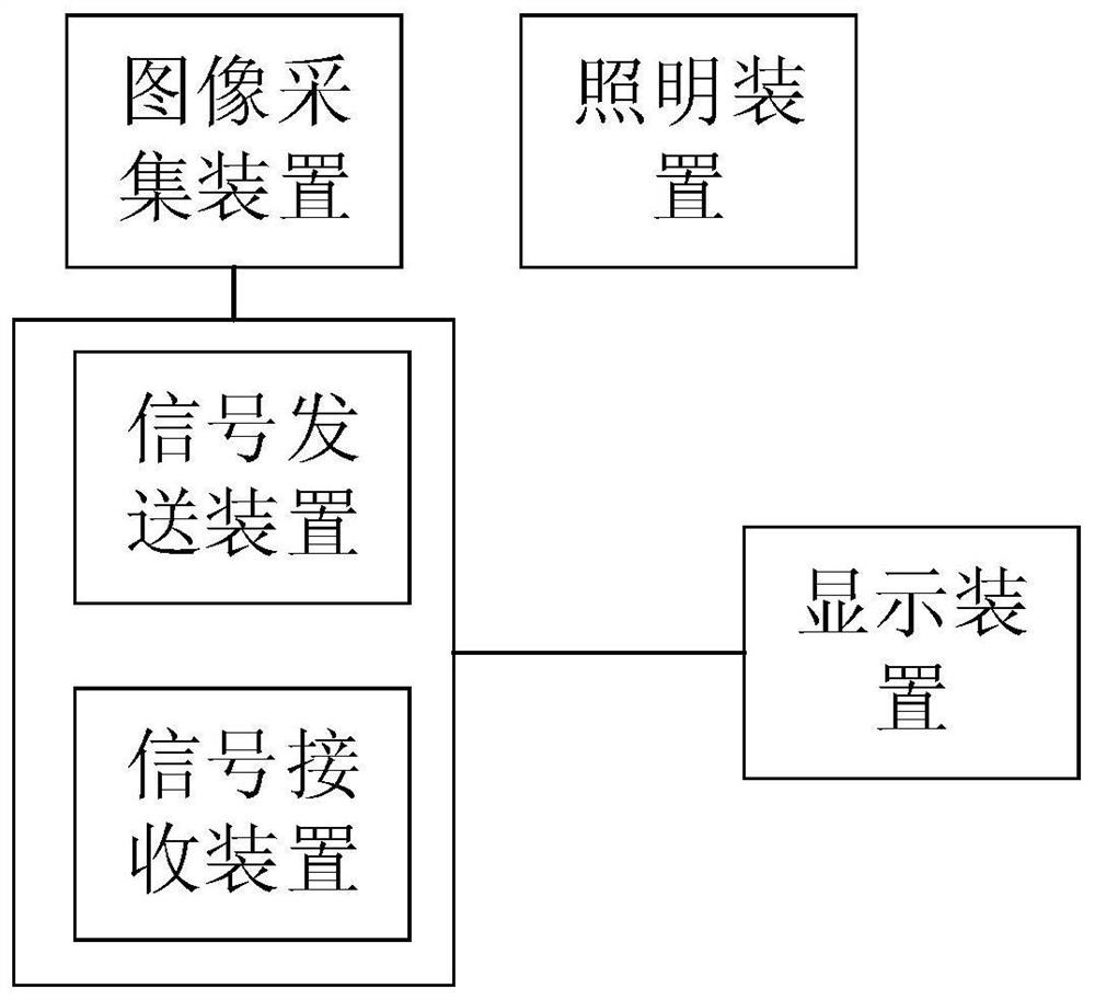
[0026] See figure 1 , figure 1 It is a block diagram of a deep-sea video shooting and wireless transmission integrated system module provided by the embodiment of the present invention, including:

[0027] an illuminating device, configured to provide an illuminating light source of a first wavelength;

[0028] An image acquisition device, configured to acquire image information with the assistance of the illumination light source;

[0029] a signal sending device, configured to send the image information to a signal receiving device with a communication light source of a second wavelength;

[0030] The signal receiving device is used to receive the communication optical signal and output image information;

[0031] a display device for displaying the image information;

[0032] Wherein, the first wavelength is greater than the second wavelength.

[0033] In a specific implementation, the lighting device is generally an auxiliary light set in water or deep sea to illumina...

Embodiment 2

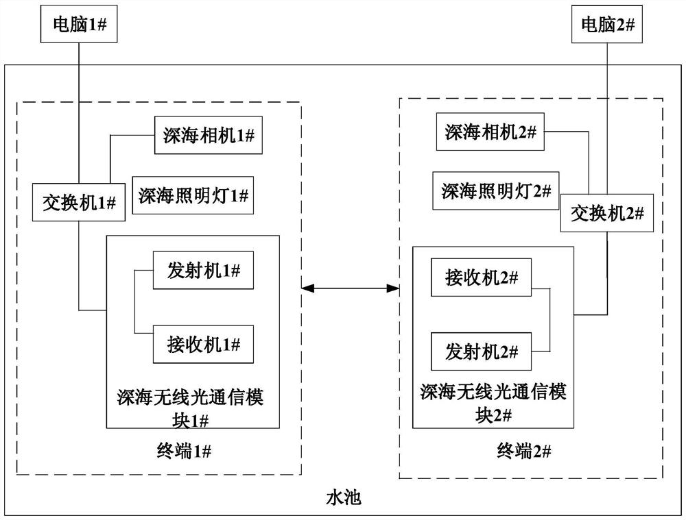
[0048] This embodiment demonstrates the solution of the present invention through an example. See figure 2 , figure 2 It is a schematic diagram of a specific example scenario provided by the embodiment of the present invention. In the example, two identical terminals are included. The distance between the two terminals is 9 meters, and the water quality attenuation coefficient in the pool is about 0.4m -1 .

[0049] Each terminal is composed of a deep-sea camera, a deep-sea light, a transmitter, a receiver, a switch, and a computer. The computer is located above the water surface, and the rest is located in the water. The various parts in each terminal are connected by watertight connecting wires.

[0050] The role of each component in the terminal is as follows:

[0051] Deep Sea Lights: Provides underwater lighting brightness. Using LED as the light source, the central wavelength is 470nm, the full width at half maximum of the spectrum is 30nm, and the luminous power...


PUM


Abstract

The invention discloses a deep-sea video shooting and wireless transmission integrated system, wherein the system comprises an illumination device which is used for providing an illumination light source with a first wavelength; an image acquisition device which is used for acquiring image information under the assistance of the illumination light source; a signal transmitting device which is used for transmitting the image information to the signal receiving device through a communication light source with a second wavelength; a signal receiving device which is used for receiving the communication optical signal and outputting image information; and a display device which is used for displaying the image information; wherein the first wavelength is greater than the second wavelength. According to the deep-sea video shooting and wireless transmission integrated system, a light source with the wavelength smaller than that of illumination is selected as a communication light source, the interference problem of illumination light is solved through a method that an interference type optical filter is arranged in a communication receiver, and the problems of deep-sea video shooting and real-time transmission can be solved.

Description

technical field [0001] The invention belongs to the field of underwater information transmission, and in particular relates to an integrated system of deep-sea video shooting and wireless transmission. Background technique [0002] The deep sea refers to the deep waters in the ocean, in this vast space there are rich biological and mineral resources. In recent years, with the increasing shortage of land resources, countries all over the world have increased the exploration and development of deep sea. However, due to the extreme water pressure of tens of megapascals or even hundreds of megapascals in the deep sea, humans cannot directly carry out work. Mobile platforms such as underwater vehicles (AUV) carry out deep sea operations. Moreover, as the difficulty of the operation increases, two or more mobile platforms often need to work together to efficiently complete the underwater operation task. [0003] In the process of close-range joint operations of deep-sea mobile ...

Claims


Application Information

Patent Timeline
IPC IPC(8): H04N5/225H04N5/38H04N5/44H04N7/18
CPCH04N5/38H04N5/44H04N7/18H04N23/55
Inventor 韩彪孙艳玲马琳鲁振中廖家莉
Owner XIDIAN UNIV
Why Eureka
Try Eureka