Split-flow treatment device for sewage treatment

A treatment device and sewage treatment technology, which is applied in the direction of filtration separation, separation method, fixed filter element filter, etc., can solve the problems of time-consuming and labor-intensive moving process, easy blockage of filter plate, increased labor intensity of staff, etc., to reduce labor intensity , the effect of preventing filter hole clogging

Inactive Publication Date: 2021-05-25
江芳
View PDF1 Cites 3 Cited by
  • Summary
  • Abstract
  • Description
  • Claims
  • Application Information

AI Technical Summary

Problems solved by technology

The diversion device cannot automatically clean the diverted and filtered waste when it is in use, and it needs to be cleaned manually, which increases the labor intensity of the staff. The board is easy to block, which affects the use, and some small and medium-sized sewage diversion boxes are inconvenient to move when used. Now the sewage diversion box is generally moved by means of transportation. The movement of the sewage diversion box is more troublesome, and the moving process is time-consuming and laborious.

Method used


Image

  • Split-flow treatment device for sewage treatment
  • Split-flow treatment device for sewage treatment
  • Split-flow treatment device for sewage treatment

Examples


Embodiment 1

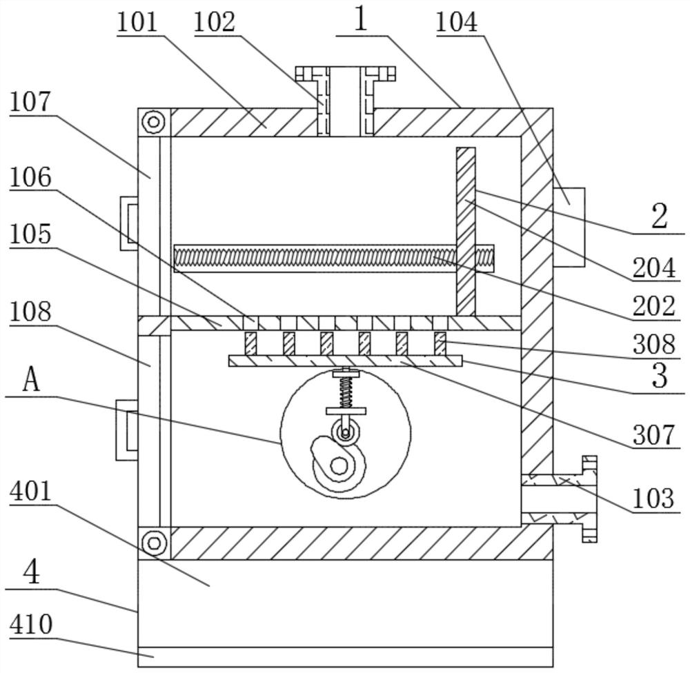
[0033] see figure 1 , image 3 , Figure 4 , Figure 5 and Figure 6 , the present invention provides a technical solution:

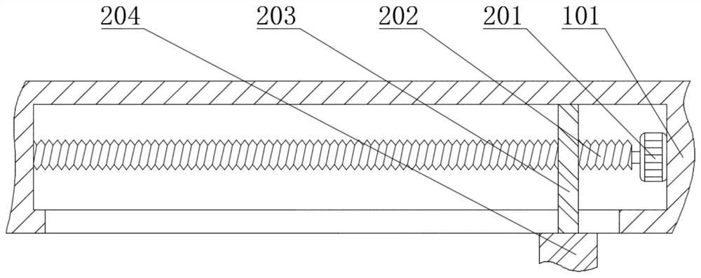
[0034]A diversion treatment device for sewage treatment, comprising a main device 1, a pushing device 2, a cleaning device 3 and a moving device 4, the main device 1 includes a diversion box 101, a controller 104 is fixedly connected to the top of the right end of the diversion box 101, and the diversion A filter plate 105 is fixedly connected to the center of the inner side of the box 101, and a filter hole 106 is opened on the filter plate 105. A first box door 107 is hinged on the top of the left end of the splitter box 101, and a second box door is hinged on the bottom of the left end of the splitter box 101. 108. The pushing device 2 includes a first motor 201, the first motor 201 is fixedly connected to the splitter box 101, the end of the main shaft of the first motor 201 is fixedly connected to a first threaded shaft 202, and the first threa...

Embodiment 2

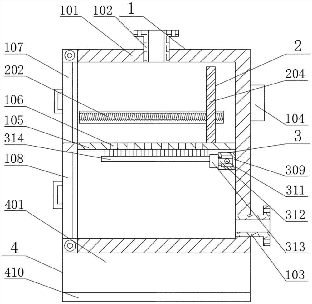
[0038] In embodiment 2, the same part as in embodiment 1 will not be repeated, please refer to the different parts figure 2 , image 3 , Figure 4 , Figure 7 and Figure 8 , the present invention provides a technical solution:

[0039] The cleaning device 3 includes a fixed plate 309 and a cleaning brush 314, the fixed plate 309 is fixedly connected with the splitter box 101, the inner side of the front end of the fixed plate 309 is fixedly connected with a third motor 310, and the end of the main shaft of the third motor 310 is fixedly connected with a second threaded shaft 311, the second threaded shaft 311 is rotationally connected with the fixed plate 309, the second threaded shaft 311 is spirally connected with the second slider 312 outside, the second slider 312 runs through the fixed plate 309, and the second slider 312 is slidably connected with the fixed plate 309 , the outer side of the second slider 312 is fixedly connected with a connecting block 313, the con...


PUM


Abstract

The invention relates to the field of sewage treatment, and particularly relates to a split-flow treatment device for sewage treatment. The split-flow treatment device comprises a main body device, a pushing device, a cleaning device and a moving device, wherein the main body device comprises a flow dividing box, a controller is fixedly connected to the top of the right end face of the flow dividing box, a filter plate is fixedly connected to the center of the inner side of the flow dividing box, filter holes are formed in the filter plate, and a first box door is hinged to the top of the left end face of the flow dividing box. According to the invention, through the arrangement of a first motor, a first threaded shaft, a first sliding block and a push plate, when much waste is accumulated on the filter plate, the first box door is opened, the first motor is controlled by a controller to rotate, the first motor rotates to drive the first threaded shaft to rotate, and the first threaded shaft drives the push plate to move through the first sliding block, so that wastes shunted and filtered on the filter plate can be automatically cleaned, and the labor intensity of workers is reduced.

Description

technical field [0001] The invention relates to the field of sewage treatment, in particular to a diversion treatment device for sewage treatment. Background technique [0002] In cities, due to the increase of population, the domestic sewage produced increases. As we all know, domestic sewage will contain a lot of waste. If the sewage is directly sent to the sewage treatment plant without preliminary treatment, it will increase the cost of the sewage treatment plant. Therefore, it is necessary to use a sewage diversion treatment device to divert the sewage, but there are some problems in the use of some sewage diversion boxes. [0003] CN201920902879.7 discloses a new type of rainwater sewage treatment diversion device, which belongs to the field of rainwater sewage treatment. A new type of rainwater sewage treatment diversion device includes a diversion well, and an inner convex ring is arranged inside the diversion well, and a drain is arranged inside the inner convex rin...

Claims


Application Information

Patent Timeline
Patent Type & Authority Applications(China)
IPC IPC(8): B01D29/03B01D29/64
CPCB01D29/03B01D29/64
Inventor 江芳
Owner 江芳
Why Eureka
Try Eureka