Building waste refining equipment
A construction waste and equipment technology, applied in the field of construction waste refinement equipment, can solve the problems of single use mode, low utilization rate, insufficient strength of concrete fragments, etc., and achieve the effect of convenient maintenance and simple structure in the later stage
- Summary
- Abstract
- Description
- Claims
- Application Information
AI Technical Summary
Problems solved by technology
Method used
Image

Examples
Embodiment 1
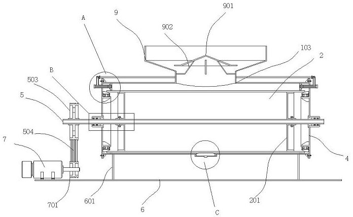
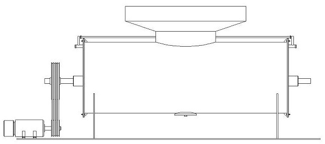
[0034]A kind of equipment for refining construction waste, comprising a cylindrical casing 1, the casing 1 is arranged laterally, a cylindrical grinding body 2 is arranged inside the casing 1, the inner wall of the casing 1 and the grinding body 2 The outer walls are all provided with grinding surfaces, and the grinding surfaces are composed of net knurling; the grinding body 2 and the casing 1 are arranged eccentrically, the axis of the grinding body 2 is lower than the axis of the casing 1, and the The axis of the grinding body 2 is parallel to the axis of the housing 1; a grinding gap 3 is formed between the grinding body 2 and the housing 1, and the width of the grinding gap 3 gradually decreases from top to bottom; The two ends of the flange are connected with end caps 4, and the shaft center of the end cap 4 is interspersed with a rotating shaft 5, and the rotating shaft 5 passes through the grinding body 2, and two pieces are arranged on the left and right inside the gri...
Embodiment 2
[0037] A convex rib 111 is arranged in the upper semi-circular arc in the housing 1, and the thickness of the convex rib 111 gradually decreases toward the direction away from the inner wall of the housing 1; broken.
Embodiment 3
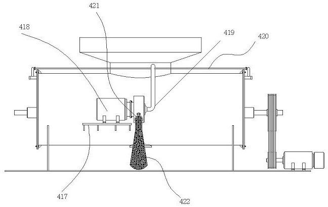
[0039] A socket 811 is provided near the top position on the side of the retaining ring 8, and a first socket 411 corresponding to the socket 811 is provided on the side of the end cover 4. 411 is inserted with a discharge pipe 412, the end of the discharge pipe 412 passing through the end cover 4 is inserted into the jack 811, and the outer wall of the discharge pipe 412 is sleeved with a rubber material Limit ring 413, the limit ring 413 contacts the end face of the retaining ring 8, the end of the discharge pipe 412 located outside the end cover 4 is threaded with a first pipe cover 414, the discharge pipe 412 is welded with a standpipe 415 at the part outside the end cover 4, and a connected elbow 416 is welded at the outer wall of the standpipe 415; a frame plate 417 is welded at the outer wall of the shell 1, and The top of the frame plate 417 is equipped with a negative pressure blower 418, the negative pressure blower 418 is connected with an extraction pipe 419, and t...
PUM
 Abstract
Description
Claims
Application Information
 - Generate Ideas
- Intellectual Property
- Life Sciences
- Materials
- Tech Scout
- Unparalleled Data Quality
- Higher Quality Content
- 60% Fewer Hallucinations
Browse by: Latest US Patents, China's latest patents, Technical Efficacy Thesaurus, Application Domain, Technology Topic, Popular Technical Reports.
© 2025 PatSnap. All rights reserved.Legal|Privacy policy|Modern Slavery Act Transparency Statement|Sitemap|About US| Contact US: help@patsnap.com