AIR purifying apparatus

An air purification device and air technology, applied in chemical instruments and methods, external electrostatic separators, power supply technology, etc., can solve problems such as increased air resistance, decreased dust collection rate, and decreased purification efficiency.

Active Publication Date: 2021-05-25
朴镇殷
View PDF17 Cites 0 Cited by
  • Summary
  • Abstract
  • Description
  • Claims
  • Application Information

AI Technical Summary

Problems solved by technology

[0003]The filter screen type adopts the method of using the air supply device to inhale the air and use the filter screen to filter the dust in the air, but it has air resistance when the dust accumulates The problem of increasing and thus reducing the purification efficiency
[0004]The electrostatic precipitator adopts the method of making the dust in the air pass through the ionization space and adsorbing it on the electrode of the dust collection part, but it has The air flow rate is too fast, resulting in a decrease in the dust collection rate of dust, etc., which leads to a decrease in the air purification efficiency
[0005] In order to solve the above-mentioned problems, a wet air purification method using water has recently been disclosed by using water supply pipes formed staggeredly on the front upper side of the water filter part, the inside of the water filter, and the water supply pipe part formed on the upper part between the water filter and the water removal filter, sp...

Method used


Image

  • AIR purifying apparatus
  • AIR purifying apparatus
  • AIR purifying apparatus

Examples


Embodiment Construction

[0044] The objects, features, and advantages of the present invention as described above will be further clarified by the following detailed description. Next, the preferred embodiments applicable to the present invention will be described in detail as follows with reference to the accompanying drawings.

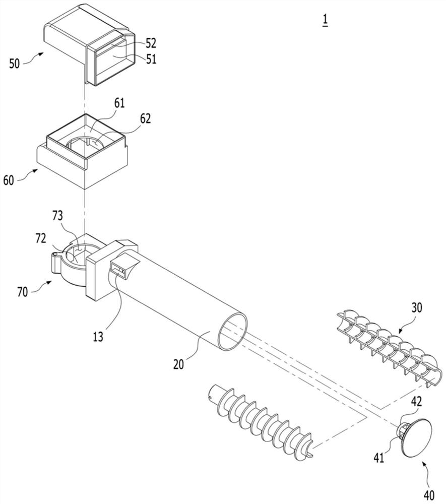
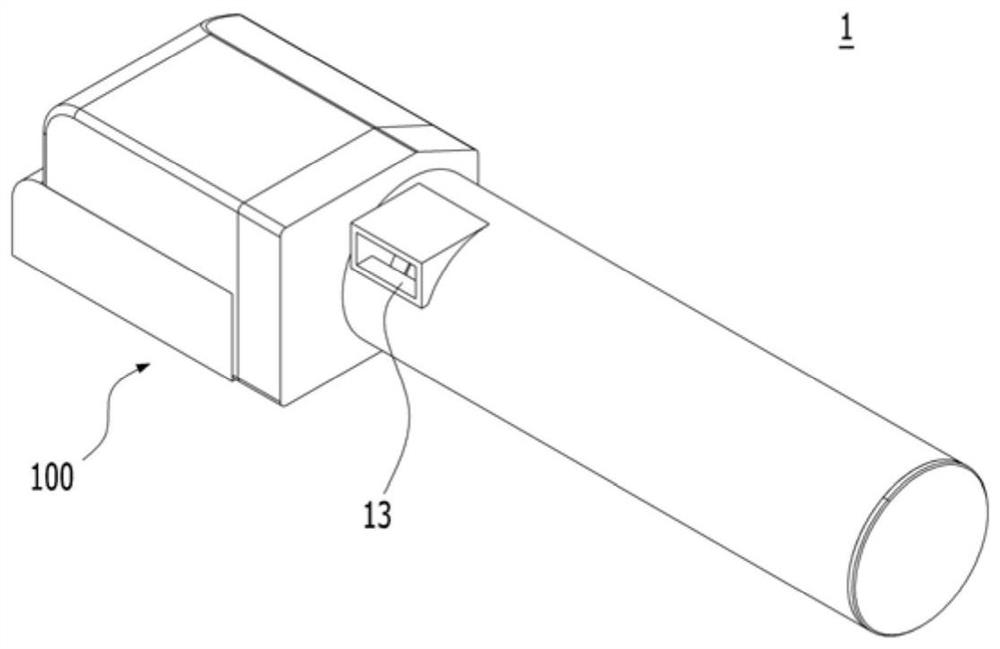
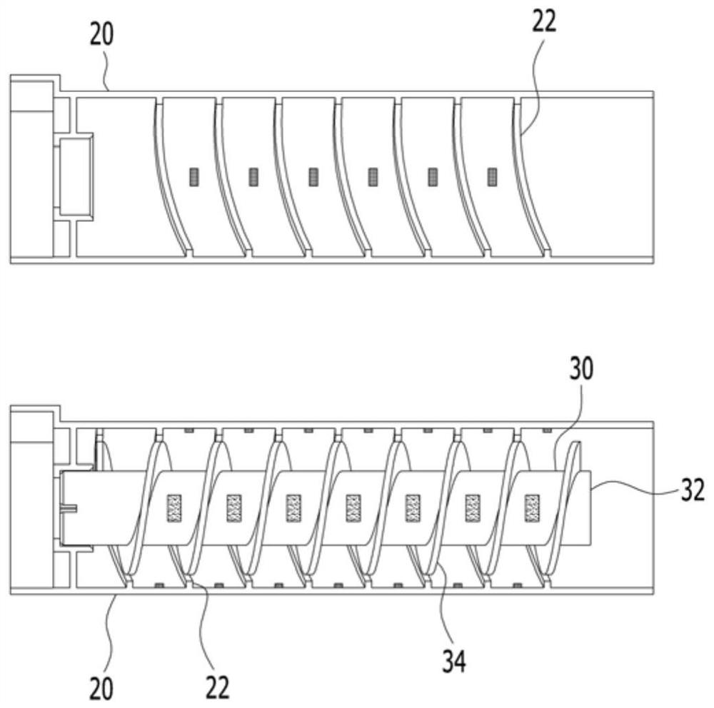
[0045] Figure 1 to Figure 6 It is a schematic diagram illustrating an air cleaning device to which an embodiment of the present invention is applied.

[0046] The air purification device applicable to the present invention includes: a tube body, a first air outlet is formed on the left side of the hollow inner body and an air inflow port is formed on the right side, and a threaded outer pin of the tube body and a cathode component are formed on the outer peripheral surface; Sleeve, the above-mentioned pipe body is installed on the inner side of the hollow outer body and an air suction port is formed on one side, and a first air discharge port coupling hole for the above-me...


PUM


Abstract

The present invention relates to an air purifying apparatus comprising: a tube in which a first air outlet is formed in the left side of a hollow internal body, an air inlet is formed in the right side thereof, and a spiral tube outer fin and a negative member are formed on the outer circumferential surface thereof; a casing in which the tube is installed inside a hollow outer body, an intake port is formed at one side thereof, a first air outlet coupling hole penetrated by the first air outlet is formed at the other side thereof, and a spiral casing fin and a positive member are formed on the inner circumferential surface thereof; a blowing fan which is installed in the first air outlet coupling hole or the intake port of the casing in order to discharge air from the first air outlet or introduce air to the intake port; and a discharging device in which harmful substances are ionized by charging between the positive member and the negative member. Thus, the air purifying apparatus can push heavy harmful substances to the outside (inner circumference of the casing) of the tube as the air introduced through the intake port rotates along an air path between the tube outer fin and the casing fin and at the same time, can charge the positive member and the negative member by ultra-high voltage of DC 3-20 kV to ionize the pushed back harmful substances and attach the same to the positive member on the inner circumferential surface of the casing. Therefore, the air purifying apparatus can maximize air purifying efficiency.

Description

technical field [0001] The present invention relates to an air cleaning device, in particular to a device capable of rotating the air flowing in through the suction port so that the heavy harmful substances contained in the air move to the outside of the tube body (anode) under the action of centrifugal force. Component side), and at the same time, the ionized harmful particles are attached to the anode part by applying an ultra-high voltage of DC 3kV to 20kV, thereby maximizing the air purification effect of the air purification device. Background technique [0002] Generally, an air purification device is a device that purifies the air in a limited space by removing impurities in the air such as dust, and a general air purification device adopts a dry air purification method such as a filter screen type or an electrostatic dust collection type. [0003] The filter screen type adopts the method of using the air supply device to inhale the air and use the filter screen to fi...

Claims


Application Information

Patent Timeline
IPC IPC(8): B03C3/15B03C3/017
CPCB03C3/15B03C3/017B03C3/368B03C3/66B03C3/155
Inventor 朴镇殷
Owner 朴镇殷
Why Eureka
Try Eureka