Metal strip edge rolling equipment for hardware factory

A metal strip and factory technology, applied in the field of metal strip rolling equipment used in hardware factories, can solve the problems of low processing efficiency, time-consuming and laborious, and inconvenient operation, and achieve the effects of convenient operation, improved operation safety, and simple structure

Active Publication Date: 2021-05-25
佛山市兴威五金有限公司
View PDF6 Cites 0 Cited by
  • Summary
  • Abstract
  • Description
  • Claims
  • Application Information

AI Technical Summary

Problems solved by technology

[0004] In order to overcome the shortcomings of inconvenient operation, time-consuming and labor-intensive work, and low processing efficiency, the technical problem to be solved is: to provide a metal bar rolling equipment for hardware factories that can improve work efficiency and has a simple structure and flexible operation

Method used


Image

  • Metal strip edge rolling equipment for hardware factory
  • Metal strip edge rolling equipment for hardware factory
  • Metal strip edge rolling equipment for hardware factory

Examples


Embodiment 1

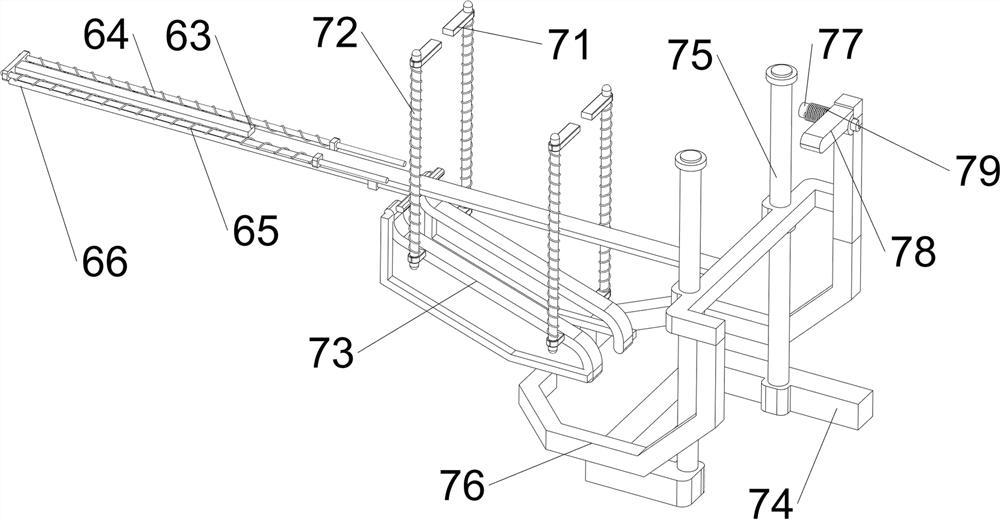
[0025] A metal bar rolling equipment for hardware factories, such as figure 1 , figure 2 As shown, it includes a base 1 , a displacement mechanism 2 and a processing mechanism 3 , the displacement mechanism 2 is provided on the top of the base 1 , and the processing mechanism 3 is provided on the front side of the base 1 .

[0026] Start the processing mechanism 3, move down through the displacement mechanism 2, place the metal strip on the processing mechanism 3 and roll it into a circle, so as to achieve the effect of easy operation, and close the processing mechanism 3 after the operation is completed.

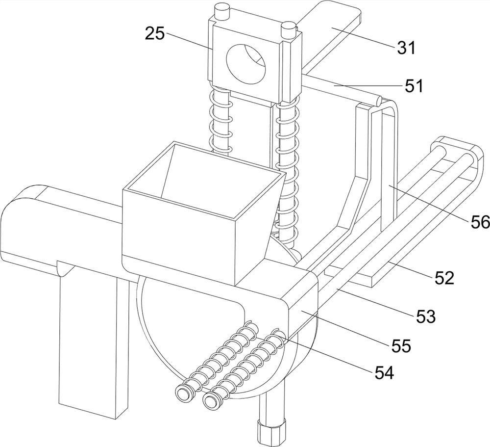
[0027] The displacement mechanism 2 includes a cylinder 21, a first slide rail 22, a first guide rod 23, a first spring 24, and a first slide block 25. The base 1 is provided with a cylinder 21 on the rear side, and the top of the base 1 is provided with a first slide rail. 22. First guide rods 23 are symmetrically arranged in the first slide rail 22, and first sliders 25...

Embodiment 2

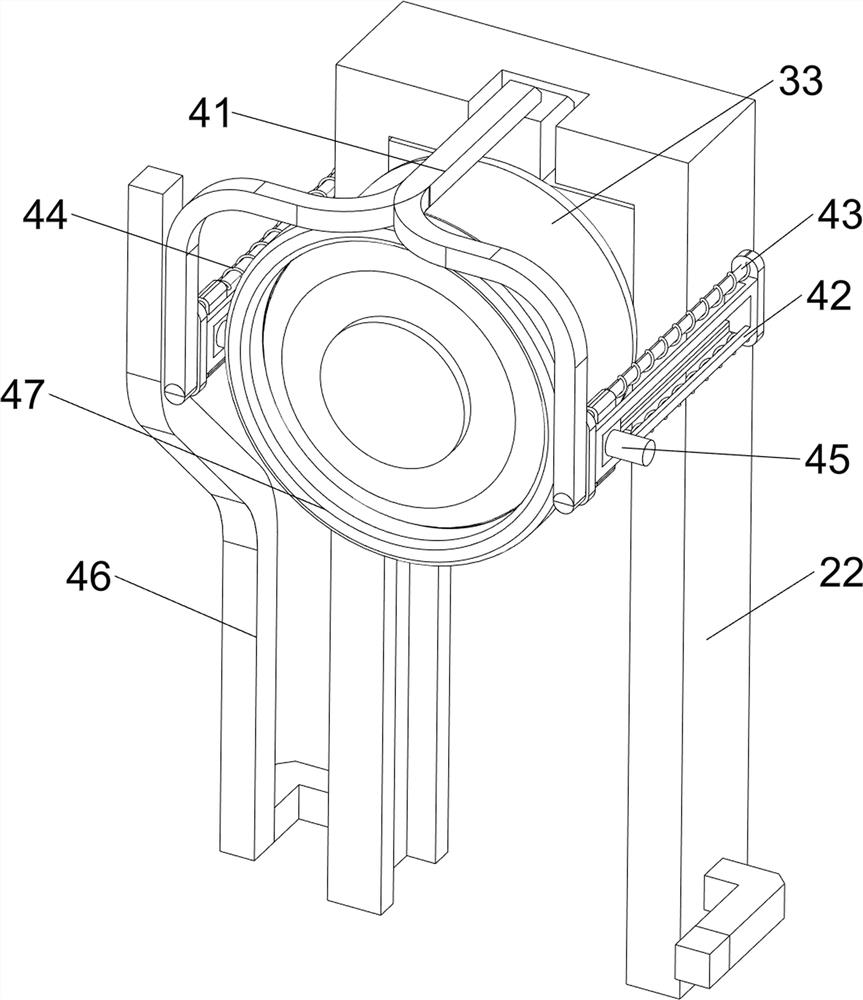
[0031] On the basis of Example 1, such as Figure 3-Figure 6 As shown, it also includes a material return mechanism 4, and the material return mechanism 4 includes a second mounting frame 41, a second slide rail 42, a second guide rod 43, a second spring 44, a second slide block 45, a guide rail 46 and a limiter. The bit ring 47, the top of the first slider 25 is provided with a second mounting frame 41, the rear side of the second mounting frame 41 is symmetrically provided with a second slide rail 42, and the second slide rail 42 is symmetrically provided with a second guide rod 43 up and down. , the second guide bar 43 is slidably provided with a second slider 45, the second slider 45 is connected to the second slide rail 42 in a sliding manner, and the second slider 45 and the second slide rail 42 are vertically symmetrical A second spring 44 is provided, and the second spring 44 is respectively sleeved on the second guide rod 43. The left and right symmetrical guide rails...


PUM


Abstract

The invention relates to edge rolling equipment, and particularly relates to metal strip edge rolling equipment for a hardware factory. The invention aims to provide the metal strip edge rolling equipment for the hardware factory, and the metal strip edge rolling equipment for the hardware factory can improve working efficiency and is simple and convenient in structure and flexible to operate. According to the technical scheme, the metal strip edge rolling equipment for the hardware factory comprises a base, a displacement mechanism and a machining mechanism, wherein the displacement mechanism is arranged on the base; and the machining mechanism is arranged on one side of the base. According to the metal strip edge rolling equipment for the hardware factory, a motor output shaft drives a first rolling wheel to rotate, a metal strip is placed on a second rolling wheel when an air cylinder piston rod drives the first rolling wheel to move downwards, when the rotating first rolling wheel makes contact with the second rolling wheel, the metal strip is rolled on the first rolling wheel to complete edge rolling machining, and the effects of being simple in structure and convenient to operate are achieved.

Description

technical field [0001] The invention relates to a rolling device, in particular to a metal bar rolling device used in a hardware factory. Background technique [0002] Metal strip processing is widely used in the industry. However, the existing metal strips have poor processing effects during the processing process, resulting in inconvenient processing and poor equipment performance, resulting in troublesome use and no good use environment; equipment Inconvenient operation, inconvenient installation and use make the processing process unable to provide convenience, which is time-consuming and laborious; poor stability, inconvenience in the processing process leads to low processing efficiency. [0003] Therefore, it is necessary to design a metal strip rolling equipment for metal factories that can improve work efficiency and has a simple structure and flexible operation. Contents of the invention [0004] In order to overcome the shortcomings of inconvenient operation, t...

Claims


Application Information

Patent Timeline
Patent Type & Authority Applications(China)
IPC IPC(8): B21D7/08B21D7/16B21D45/04B21D43/20
CPCB21D7/08B21D7/16B21D45/04B21D43/20Y02P70/10
Inventor 王光会
Owner 佛山市兴威五金有限公司
Why Eureka
Try Eureka