Precise perforating equipment used for notebook computer bottom plate

A technology for punching equipment and notebooks, which is applied in the direction of drilling/drilling equipment, metal processing equipment, boring/drilling, etc., which can solve the problem of low safety and achieve the effect of easy collection and good fixation

Pending Publication Date: 2021-05-25
何家焕
View PDF0 Cites 5 Cited by
  • Summary
  • Abstract
  • Description
  • Claims
  • Application Information

AI Technical Summary

Problems solved by technology

[0004] In order to overcome the shortcomings of the existing technology that the bottom plate needs to be manually pushed and the safety is low, the technical problem to be solved is to provide a notebook bottom plate precision printing machine with a high degree of automation, high safety and the ability to clean the bottom plate. hole equipment

Method used


Image

  • Precise perforating equipment used for notebook computer bottom plate
  • Precise perforating equipment used for notebook computer bottom plate
  • Precise perforating equipment used for notebook computer bottom plate

Examples


Embodiment 1

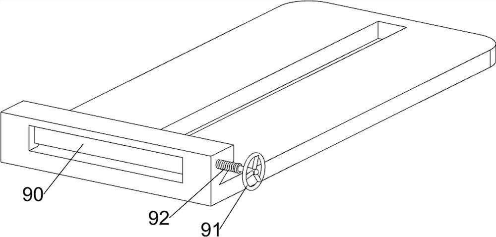
[0029] A device for precise punching of notebook bottom plates, such as figure 1 and figure 2 As shown, it includes a base 1, an operating table 2, a punching mechanism 3 and a clamping mechanism 4. The base 1 is provided with an operating table 2, the operating table 2 is provided with a punching mechanism 3, and the punching mechanism 3 is provided with a clamping mechanism. Tight mechanism4.

[0030] When people need to use this equipment, first people place the bottom plate on the right side of the console 2, then people can start the punching mechanism 3, and the punching mechanism 3 operates to punch holes on the left side of the bottom plate, while the punching mechanism 3 drives The clamping mechanism 4 operates, so that the clamping mechanism 4 clamps the bottom plate, and then after the left side of the bottom plate is punched, the punching mechanism 3 moves upward to separate from the bottom plate, and the punching mechanism 3 moves upward so that the clamping mec...

Embodiment 2

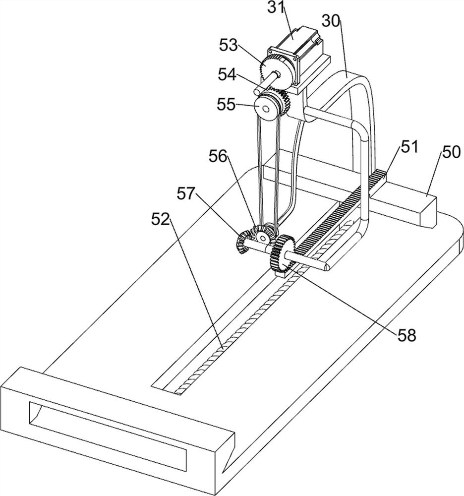
[0035] On the basis of Example 1, such as figure 1 , image 3 , Figure 4 , Figure 5 , Figure 6 and Figure 7 Shown, also comprise propulsion mechanism 5, and propulsion mechanism 5 comprises push block 50, rack 51, the 3rd spring 52, missing gear 53, first full gear 54, transmission assembly 55, first bevel gear 56, second bevel Gear 57 and the second full gear 58, sliding type is provided with push block 50 on the console 2, is provided with rack 51 on the push block 50, is provided with the 3rd spring 52 between push block 50 and console 2, servomotor 31 The output shaft is provided with a missing gear 53, and the first full gear 54 is rotatably arranged on the supporting seat 30. The first full gear 54 meshes with the missing gear 53, and the supporting seat 30 is rotatably provided with a first bevel gear 56. 30 upper rotary type is provided with the second bevel gear 57, is provided with transmission assembly 55 between the first bevel gear 56 and the first full g...


PUM


Abstract

The invention relates to perforating equipment, in particular to precise perforating equipment used for a notebook computer bottom plate. The precise perforating equipment used for the notebook computer bottom plate is high in automation degree, high in safety and capable of cleaning the bottom plate. The precise perforating equipment used for the notebook computer bottom plate comprises a base, a perforating mechanism and a clamping mechanism. An operation table is arranged on the base. The perforating mechanism is arranged on the operation table. The clamping mechanism is arranged on the perforating mechanism. The bottom plate is clamped through the clamping mechanism, and then the bottom plate is perforated under cooperation with the perforating mechanism; and a pushing mechanism is arranged, and then the bottom plate is automatically pushed leftwards.

Description

technical field [0001] The invention relates to a punching device, in particular to a precise punching device for a bottom plate of a notebook. Background technique [0002] The bottom plate is usually used as the installation part at the bottom of the machine, and because the fixing between the parts is mostly carried out by screws, so it is necessary to open more holes on the bottom plate, the existing punching device usually needs to manually place the bottom plate on the On the workbench, the punching device is then operated to punch holes on the bottom plate. After the punching of one part of the bottom plate is completed, the bottom plate needs to be pushed manually so that the punching device can punch holes in different parts of the bottom plate. However, people manually push the bottom plate. The distance of each push is different, so it is easy to make the position of the punching hole different, which will affect the installation position of the parts, and because...

Claims


Application Information

Patent Timeline
Patent Type & Authority Applications(China)
IPC IPC(8): B23B41/00B23B39/16B23B47/20B23Q3/06B23Q7/00B23Q11/00
CPCB23B39/161B23B41/00B23Q3/062B23Q5/36B23Q7/00B23Q11/0042
Inventor 何家焕
Owner 何家焕
Why Eureka
Try Eureka