Wood board-cutting equipment for production and manufacturing
A technology for cutting boards and equipment, applied in sawing equipment, manufacturing tools, sawing components, etc., can solve the problems of cumbersome operation process, low worker safety factor, low work efficiency, etc. good cutting effect
- Summary
- Abstract
- Description
- Claims
- Application Information
AI Technical Summary
Problems solved by technology
Method used
Image
Examples
Embodiment 1
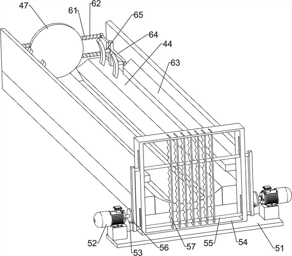
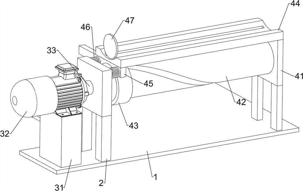
[0025]Wood cutting board equipment for production, such asFigure 1-3As shown, including the bottom plate 1, the support post 2, the power mechanism 3, the push mechanism 4, and the cutting mechanism 5, the upper left side of the bottom plate 1 is connected to the upper left side of the bottom plate 1 connected to the left side of the bottom plate 1, support column 2 The push mechanism 4 is connected to the front side of the push mechanism 4 is connected to the cutting mechanism 5.
[0026]The power mechanism 3 includes a support base 31, a servo motor 32, and a rotating shaft 33, and the upper left rear side of the bottom plate 1 is connected to the support base 31, and the support base 31 is connected to the servo motor 32, and the servo motor 32 is connected to the shaft 33.
[0027]The push mechanism 4 includes a support plate 41, a roller 42, a circular slider 43, a discharge block 44, a push plate 45, a first spring 46, and a pressing plate 47, and a support sheet 2 is connected to t...
Embodiment 2
[0031]On the basis of Example 1, such asimage 3 The clamping mechanism 6 is further included, the clamping mechanism 6 includes a guide bar 61, a second spring 62, a restricted plate 63, a push rod 64, and a clamping block 65, and a guide plate 47. 61. The guide bar 61 is slidably connected to the push rod 64, and the pressing plate 47 is connected between the push rod 64, and the discharge block 44 is connected to the finisher plate 63, the push rod 64 and the limit The plate 63 is in contact with the push rod 64, and the clamping block 65 is located above the discharge block 44.
[0032]When the pressing plate 47 moves, the guide bar 61 moves forward by the push rod 64, and the clamping block 65 is close to the position plate 63, the pressing plate 47 continues to move, under the action of the limit plate 63 The push rod 64 slides on the guide bar 61, the second spring 62 compresses, the clamping block 65 will limit the wood to the wood, to ensure that the wood will not be shake duri...
Embodiment 3
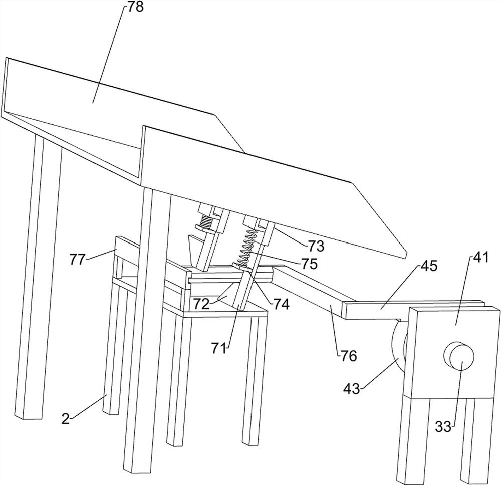
[0034]On the basis of Example 2, such asFigure 4 As shown, it is also included with a sheet of material 7, and the lower material 7 includes a sheet 71, a limiting block 72, a wedge block 73, a fixed block 74, a guide block 75, a third spring 76, a squeezing block 77, and a guide rail. 78. The upper plate 71 is connected to the right side of the bottom plate 1. The bottom plate 71 is connected to the guide block 75, and the guide block 75 is slidably connected to the finite block 72, and the limit block 72 is connected to the bottom of the wedge block 73, the limit A fixed block 74 is connected to the bit block 72, and the fastening block 74 is connected between the fixing block 74 and the guide block 75, and the push plate 45 is connected to the right side, and the bottom plate 1 is connected in the middle of the bottom plate 78, and the extrusion block is connected. 77 slides on the guide rail 78.
[0035]Place the wood in the lower plate 71, by the right limit plate 63, when the pla...
PUM
 Abstract
Description
Claims
Application Information
 - R&D
- Intellectual Property
- Life Sciences
- Materials
- Tech Scout
- Unparalleled Data Quality
- Higher Quality Content
- 60% Fewer Hallucinations
Browse by: Latest US Patents, China's latest patents, Technical Efficacy Thesaurus, Application Domain, Technology Topic, Popular Technical Reports.
© 2025 PatSnap. All rights reserved.Legal|Privacy policy|Modern Slavery Act Transparency Statement|Sitemap|About US| Contact US: help@patsnap.com


