
Plastic packaging press

A technology of a press and a first flow channel, applied in the field of plastic sealing presses, can solve the problems of a large number of air bubbles and the inability of the plastic sealing material to fill the mold hole air, etc., and achieve the effects of reducing air bubbles, facilitating cleaning, and improving the yield rate.

Active Publication Date: 2021-05-25
华芯智造微电子(重庆)有限公司
View PDF13 Cites 1 Cited by
  • Summary
  • Abstract
  • Description
  • Claims
  • Application Information

AI Technical Summary

Problems solved by technology

[0004] The present invention aims to provide a plastic sealing press to solve the problem that in the existing plastic sealing press, there is a large amount of air in the mold hole due to the fact that the solid plastic sealing compound cannot fill the mold hole. There will be a lot of bubbles

Method used


Image

  • Plastic packaging press
  • Plastic packaging press
  • Plastic packaging press

Examples


Embodiment Construction

[0021]The following will be further described in detail below with reference to specific embodiments:

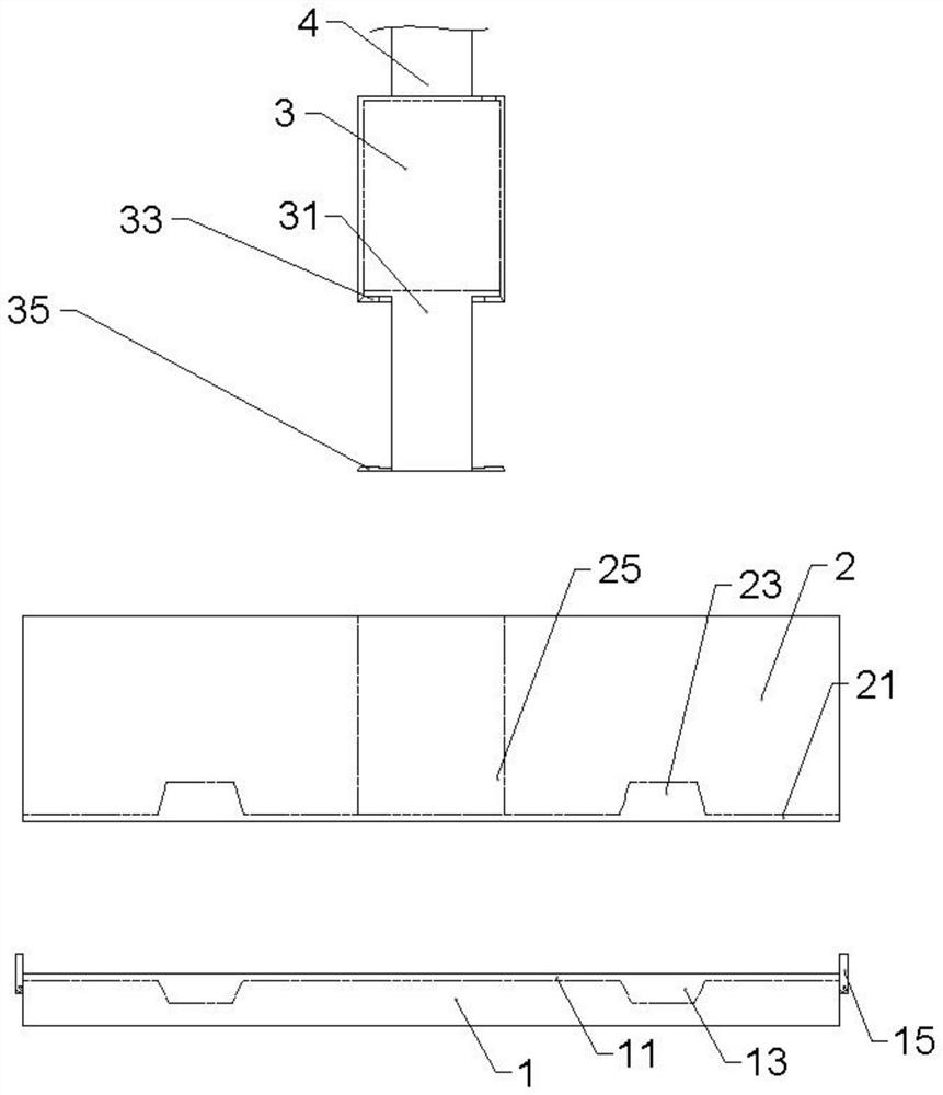
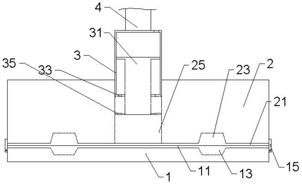
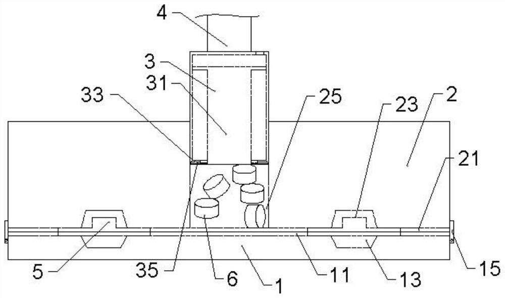
[0022]Reference numerals in the accompanying drawings include: supporting lower mold 1, first flow path 11, first placed hole 13, baffle 15, second flow channel 21, upper mold 2, second placement hole 23, feed channel 25 The second through hole 33, the injection rod 31, the outer casing 3, the blade 35, the drive rod 4, the wafer 5, and the plastic seal 6.

[0023]Embodiments are basicallyfigure 1 As shown: a plastic sealing machine, including a rack (not shown) and a plastic seal structure, the plastic structure from the bottom, in turn, the upper mold 1, upper mold 2, heating mechanism (not shown) and The injection head is fixed to the rack, and the upper mold 2 is slidably connected to the frame, and the upper mold 2 can be pressed on the support lower mold 1, and the upper surface of the upper surface 1 is opened with the first placement hole 13 and in communication. The first flow ...


PUM


Abstract

The invention relates to the technical field of semiconductor packaging equipment, and provides a plastic packaging press. The press aims to solve the problem that a large number of bubbles exist in a liquid plastic packaging material after the plastic packaging material is molten due to the fact that a solid plastic packaging material cannot fill a mold hole and a large amount of air exists in a mold in an existing plastic packaging press, and comprises a supporting lower mold, an upper mold and an injection head. The upper mold can be pressed on the supporting lower mold, the upper surface of the supporting lower mold is provided with a first containing hole and a first runner communicated with the first containing hole, the lower surface of the upper mold is correspondingly provided with a second containing hole and a second runner communicated with the second containing hole, the upper mold is further provided with a feeding channel communicated with the second runner, and the injection head is connected with a driving rod. The injection head is matched with the feeding channel and slides along the feeding channel; and the injection head comprises a shell, a sliding way is formed in the shell, an injection rod with a T-shaped longitudinal section is slidably connected into the sliding way, a first through hole communicated with the sliding way is formed at the upper end of the shell, and a second through hole communicated with the sliding way is formed in the bottom face of the shell.

Description

Technical field[0001]The present invention relates to the technical field of packaging equipment of semiconductors, in particular a plastic sealing machine.Background technique[0002]The semiconductor package refers to the process of obtaining an independent chip by the wafer that will be tested according to the product model and functional requirements. The package process is: the wafer from the wafer front process is cut into small wafers by the scribing process, and then cut the cut wafer is attached to the small island of the corresponding substrate frame, and use ultrafine Metal wire or conductive resin connects the engagement pad of the wafer to the respective pin of the substrate, and constitutes the required circuit; then the independent wafer is applied to the plastic housing to protect, and a series of operations, packages after the plastic seal After completing, the finished product test is performed, usually the process of inspection, testing and packaging, and finally sh...

Claims


Application Information

Patent Timeline
IPC IPC(8): B29C45/14B29C45/34B29C45/17B29L31/34
CPCB29C45/14647B29C45/34B29C45/1753B29L2031/3406
Inventor 杨振声
Owner 华芯智造微电子(重庆)有限公司
Learn More