Reaction tube feeding mechanism

A technology of reaction tubes and hoppers, which is applied to conveyors, conveyor objects, conveyor control devices, etc., can solve the problems of low feeding efficiency, low degree of automation, and large physical consumption of operators.

Pending Publication Date: 2021-05-25
宁波美康盛德生物科技有限公司
View PDF0 Cites 1 Cited by
  • Summary
  • Abstract
  • Description
  • Claims
  • Application Information

AI Technical Summary

Problems solved by technology

With the advancement of technology, the requirements for detection efficiency are getting higher and higher. In the assembly line detection process, the traditional reaction tube loading is manually stacked on the carrier, and then

Method used


Image

  • Reaction tube feeding mechanism
  • Reaction tube feeding mechanism
  • Reaction tube feeding mechanism

Examples


Embodiment Construction

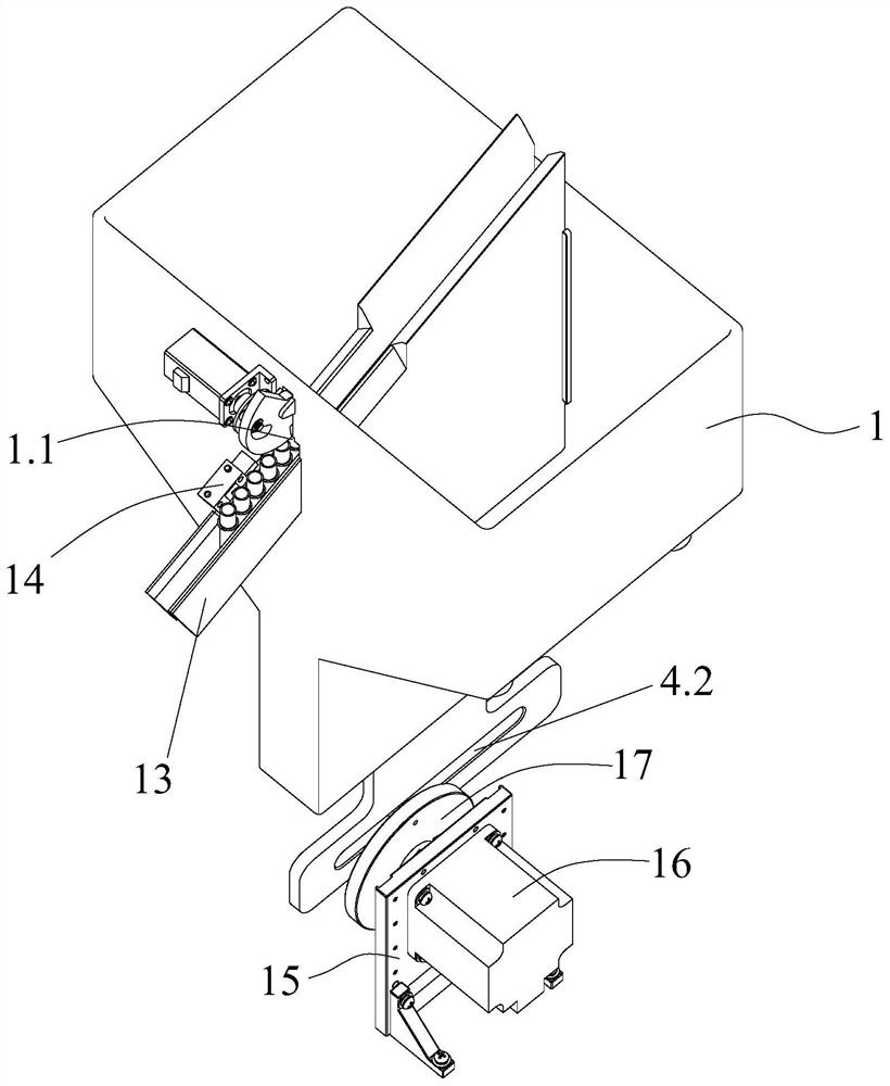
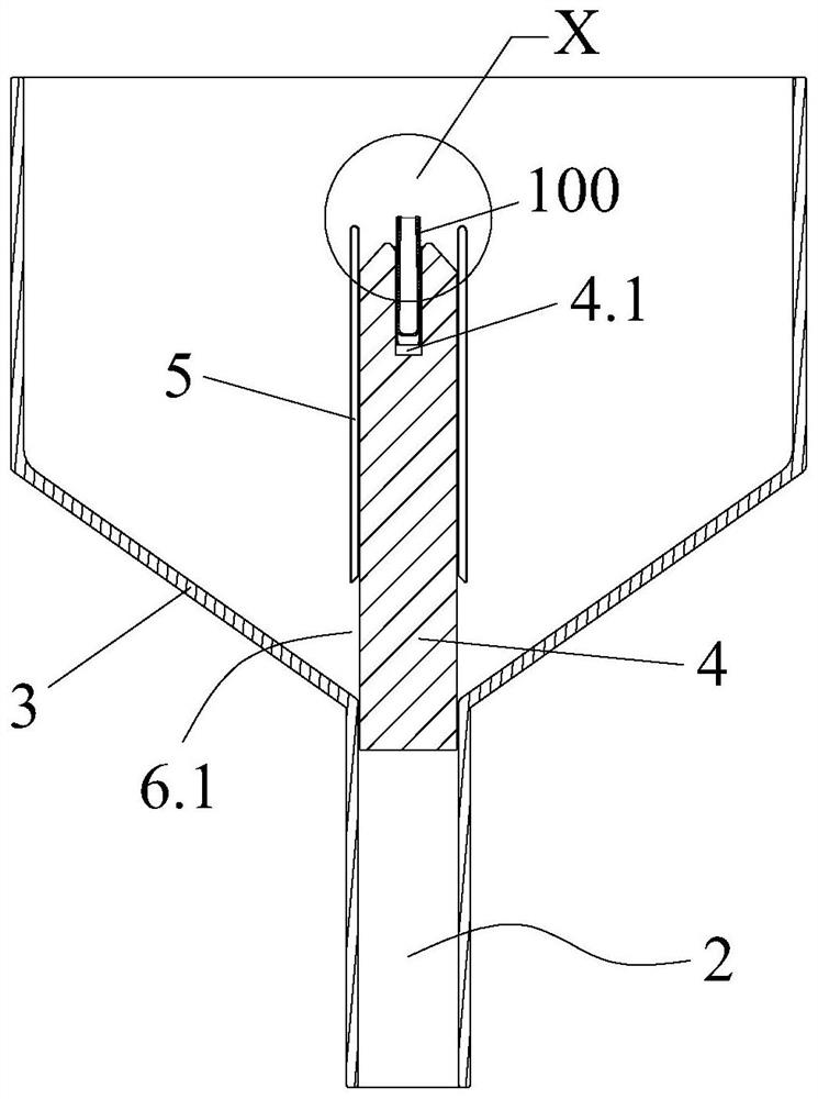
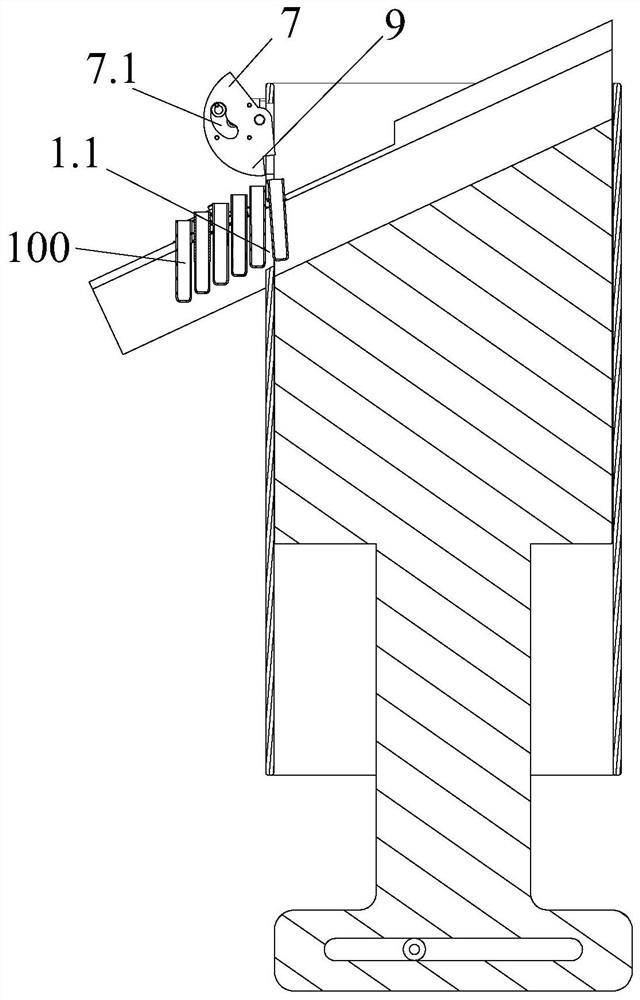
[0025] The present invention will be further described below in conjunction with the accompanying drawings and specific embodiments.

[0026] In the description of the present invention, it should be noted that the orientation or positional relationship indicated by the terms "bottom", "upper and lower", "upper end", "outer side wall", "lower end" etc. is based on the orientation or position shown in the drawings The relationship is only for the convenience of describing the present invention and simplifying the description, but does not indicate or imply that the referred device or element must have a specific orientation, be constructed and operated in a specific orientation, and thus should not be construed as a limitation of the present invention. In addition, in the description of the present invention, the terms "first" and "second" are only for convenience of description and distinction, and have no specific meaning.

[0027] In the description of the present invention,...


PUM


Abstract

The invention discloses a reaction tube feeding mechanism. The reaction tube feeding mechanism comprises a hopper, wherein a mounting hole is formed in the bottom of an inner cavity of the hopper, a pushing plate is slidably arranged in the mounting hole, and a driving assembly used for driving the pushing plate to move up and down is arranged at the lower end of the hopper; an accommodating groove for accommodating reaction tubes is formed in the upper end of the pushing plate, and the upper end surface of the accommodating groove serves as an inclined surface which is inclined outwards along the interior of the hopper; when the pushing plate moves downwards to the lowest point, the reaction tubes in the hopper enter the accommodating groove and are arranged in the vertical direction, and limiting lugs on the outer side walls of the upper ends of the reaction tubes abut against the upper end face of the accommodating groove; and when the pushing plate ascends to a first preset height, the reaction tubes in the accommodating groove slide along the inclined surface and are conveyed to a next station. The reaction tube feeding mechanism is simple in structure, high in efficiency and high in automation degree.

Description

technical field [0001] The invention relates to the technical field of medical testing instruments, in particular to a reaction tube feeding mechanism. Background technique [0002] In the medical testing instruments in the in vitro diagnostic industry, the reaction tube is an indispensable container for storing biological samples, performing reaction tests, and testing processes. With the advancement of technology, the requirements for detection efficiency are getting higher and higher. In the assembly line detection process, the traditional reaction tube loading is manually stacked on the carrier, and then transferred by the manipulator to the subsequent workflow. This traditional feeding method consumes a lot of physical energy for the operator, and the degree of automation is not high, resulting in low final feeding efficiency. Contents of the invention [0003] The technical problem to be solved by the present invention is to provide a reaction tube feeding mechanism...

Claims


Application Information

Patent Timeline
IPC IPC(8): B65G47/82B65G65/38B65G47/256B65G43/08
CPCB65G43/08B65G47/256B65G47/82B65G65/38B65G2201/0276B65G2203/042
Inventor 邹继华谢小恒徐星存吴旭峰张哲
Owner 宁波美康盛德生物科技有限公司
Why Eureka
Try Eureka