
Copper column arrangement equipment

A kind of equipment and copper column technology, applied in the field of copper column arrangement equipment, can solve the problems of unsatisfactory copper column arrangement effect, affecting the production efficiency of heat sinks, slow arrangement speed, etc., and achieve high degree of automation, high production efficiency and shaking frequency high effect

Active Publication Date: 2021-05-25
惠州市未来智能自动化设备有限公司
View PDF18 Cites 0 Cited by
  • Summary
  • Abstract
  • Description
  • Claims
  • Application Information

AI Technical Summary

Problems solved by technology

[0002]In the production process of the radiator, in order to make the heat dissipation effect of the radiator better, it is usually necessary to evenly distribute the heat conducting metal on the heat sink, because the thermal conductivity of copper metal is relatively low Strong, copper pillars are usually evenly distributed on the heat sink, the workers will prepare the various copper pillars, sintered powder pillars and fixtures to be used, and separate the copper pillars and powder pillars according to the arrangement requirements of the heat dissipation copper sheets. The speed of arranging copper columns and powder columns is very slow, and the current copper column alignment machines usually have a simple structure and a single vibration direction, which can easily make the arrangement of copper columns unsatisfactory, and the slow vibration will easily affect the production efficiency of heat sinks. In order to improve production Efficiency, innovate the structure of the alignment machine, reduce the intensity of manual work, we provide a copper column alignment equipment

Method used


Image

  • Copper column arrangement equipment
  • Copper column arrangement equipment
  • Copper column arrangement equipment

Examples


Embodiment Construction

[0020] The following will clearly and completely describe the technical solutions in the embodiments of the present invention with reference to the accompanying drawings in the embodiments of the present invention. Obviously, the described embodiments are only some, not all, embodiments of the present invention. Based on the embodiments of the present invention, all other embodiments obtained by persons of ordinary skill in the art without making creative efforts belong to the protection scope of the present invention.

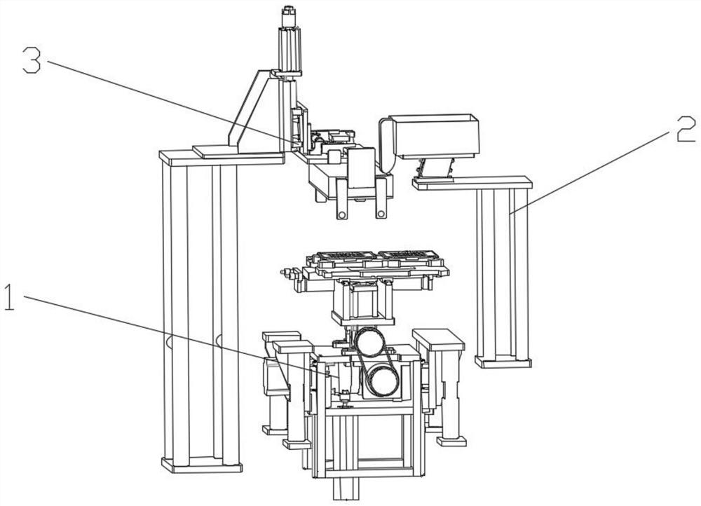
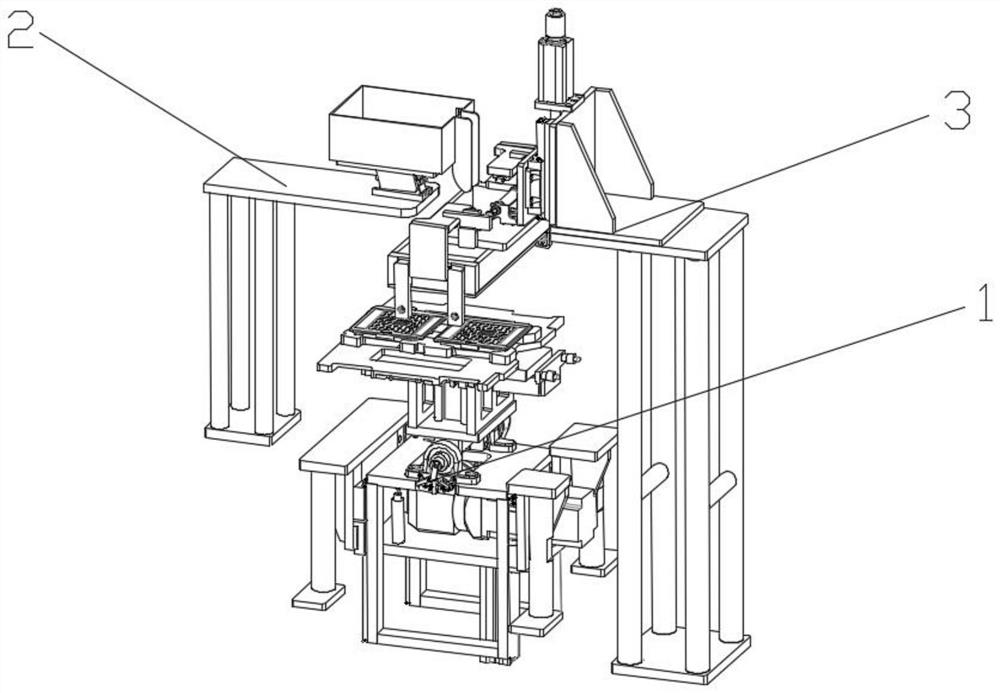
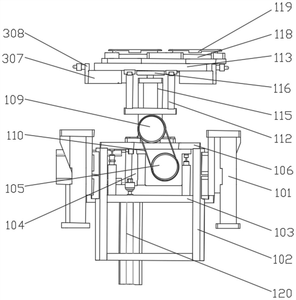
[0021] see Figure 1-7 , the present invention provides a technical solution for copper column arrangement equipment: a copper column arrangement equipment, including a shaking mechanism 1, a blanking mechanism 2 and a clamping mechanism 3, the blanking mechanism 2 and the clamping mechanism 3 are respectively set On both sides of the shaking mechanism 1, the blanking mechanism 2 makes the copper pillars to be arranged fall into the shaking mechanism 1, and th...


PUM


Abstract

The invention discloses copper column arrangement equipment, comprising a shaking mechanism, a blanking mechanism, and a clamping mechanism. The blanking mechanism and the clamping mechanism are arranged on the upper portions of the two sides of the shaking mechanism, respectively; the driving end of a stepper motor is fixedly connected with a first conveying wheel; a conveying belt is jointly arranged on the first conveying wheel and a second conveying wheel; an annular limiting member is embedded in the middle of a sliding plate in a penetrating mode; a disc is fixedly connected to the driving end of a servo motor; a sliding block is arranged at the position, deviating from the center, of the disc; the sliding block is slidably connected into the annular limiting member; a mold groove is fixedly connected to the upper side of the sliding plate; and a mold is arranged in the mold groove. The mold in the mold groove can shake in a more omnibearing manner, the shaking frequency is high, the arrangement effect of copper columns is better, the production efficiency of cooling fins is high, the copper columns can be prevented from being exposed during shaking, and the shaking process is more stable.

Description

technical field [0001] The invention relates to the technical field of radiator production equipment, and the specific field is a copper column arrangement equipment. Background technique [0002] In the production process of the radiator, in order to make the heat dissipation effect of the radiator better, it is usually necessary to evenly distribute the heat-conducting metal on the heat sink. The various copper pillars, sintered powder pillars and fixtures are ready, and the copper pillars and powder pillars are separately installed according to the heat dissipation copper sheet arrangement requirements, and the speed of manually arranging the copper pillar powder pillars is very slow, and the current Copper column alignment machines usually have a simple structure and a single vibration direction, which can easily make the arrangement of copper columns unsatisfactory, and the slow vibration can easily affect the production efficiency of heat sinks. In order to improve pro...

Claims


Application Information

Patent Timeline
IPC IPC(8): B65G65/44B65G47/26B65G47/22
CPCB65G65/44B65G47/26B65G47/22B65G2201/0214Y02P10/20
Inventor 古小洪周清华
Owner 惠州市未来智能自动化设备有限公司
Learn More