Energy-saving and environment-friendly driving and locking device for hospital radiation protection door
An energy-saving, environment-friendly, locking device technology, applied in the field of medical radiation-proof doors, can solve problems such as failure to open after power failure, radiation-proof doors are not environmentally friendly, etc., and achieve the effects of stable and reliable performance, low cost, and avoiding panic.
- Summary
- Abstract
- Description
- Claims
- Application Information
AI Technical Summary
Problems solved by technology
Method used
Image

Examples
Embodiment Construction
[0029] The following will clearly and completely describe the technical solutions in the embodiments of the present invention with reference to the accompanying drawings in the embodiments of the present invention. Obviously, the described embodiments are only some, not all, embodiments of the present invention. Based on the embodiments of the present invention, all other embodiments obtained by persons of ordinary skill in the art without making creative efforts belong to the protection scope of the present invention.
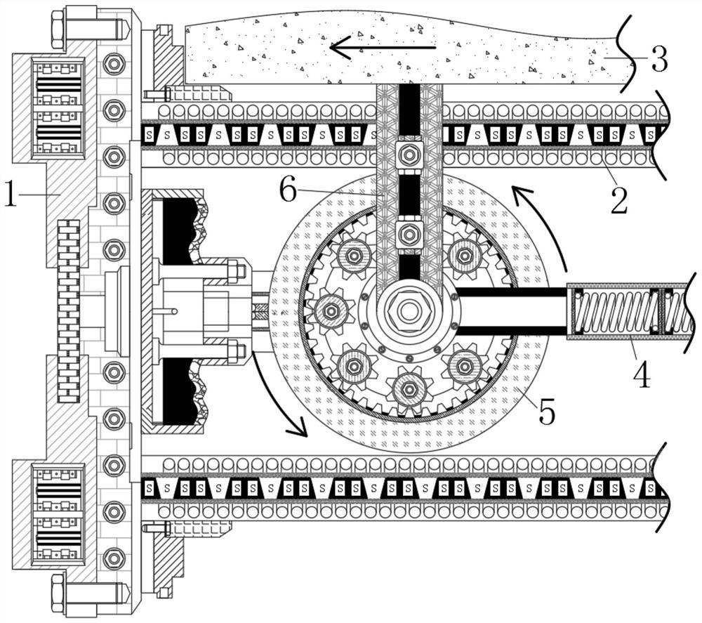
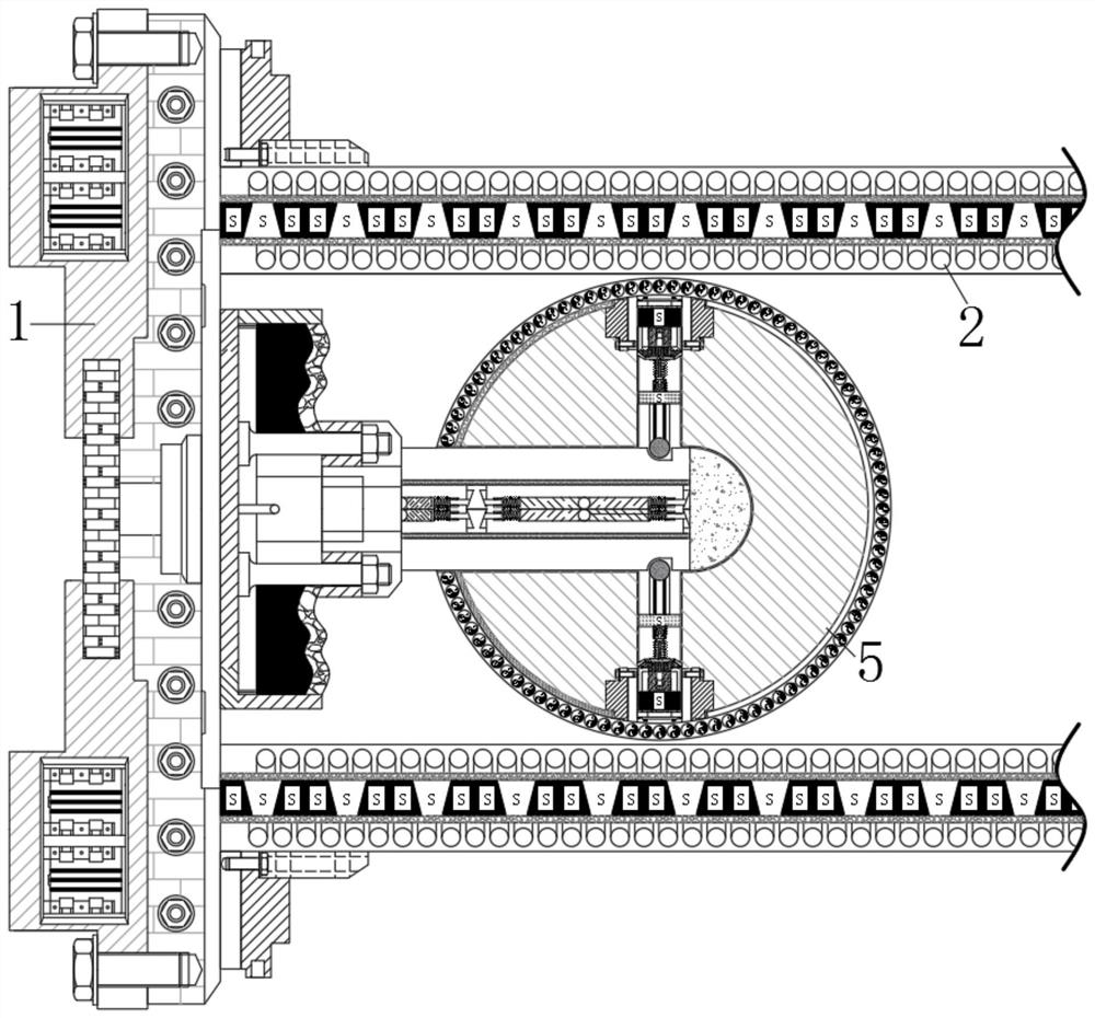
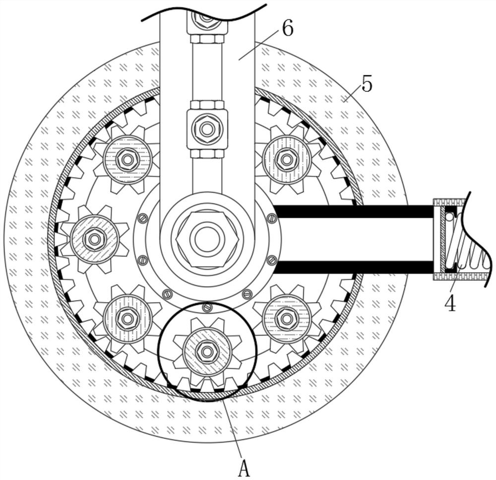
[0030] see Figure 1-9 , an energy-saving and environment-friendly driving and locking device for radiation protection doors in hospitals, comprising a fixed base 1, the outer wall of the fixed base 1 is connected with a trigger rod 7, and the outer wall of the trigger rod 7 is movably connected with a locking rod 12, the lock The opposite end of the tight rod 12 is fixedly connected with a movable magnetic block 11, and the connection mode between the movable...
PUM
 Abstract
Description
Claims
Application Information
PatSnap Eureka turns technology decisions into work you can execute. Powered by our Innovation Knowledge Graph, it runs expert workflows across engineering, life sciences, materials and intellectual property. Get your review-ready output in minutes.


