
Fluid kinetic energy negative pressure power generation system

A power generation system and negative pressure technology, which is applied in the field of fluid kinetic energy negative pressure power generation system, can solve the problems that fluid kinetic energy power generation equipment cannot stably and continuously generate power, and achieve the effect of stable and continuous power generation

Inactive Publication Date: 2021-05-25
石俊阁
View PDF0 Cites 0 Cited by
  • Summary
  • Abstract
  • Description
  • Claims
  • Application Information

AI Technical Summary

Problems solved by technology

[0004] In order to solve the above-mentioned problem, that is, the problem that the existing fluid kinetic energy power generation equipment cannot generate electricity stably and continuously, the present invention proposes a fluid kinetic energy negative pressure power generation system, which includes an energy harvesting device, a fluid kinetic energy conversion device and a power generation assembly device. The energy device includes a vertical shaft on which fan blades are arranged, and the rotating shaft of the fan blades is arranged perpendicular to the vertical shaft. The fan blades are connected to the vertical shaft through a transmission assembly, and the vertical shaft is fixedly connected to the support frame through bearings. At least one set of transmission devices is arranged on the vertical shaft. The energy harvesting device is connected with the fluid kinetic energy conversion device through the transfer device;

Method used


Image

  • Fluid kinetic energy negative pressure power generation system
  • Fluid kinetic energy negative pressure power generation system
  • Fluid kinetic energy negative pressure power generation system

Examples


Embodiment 1

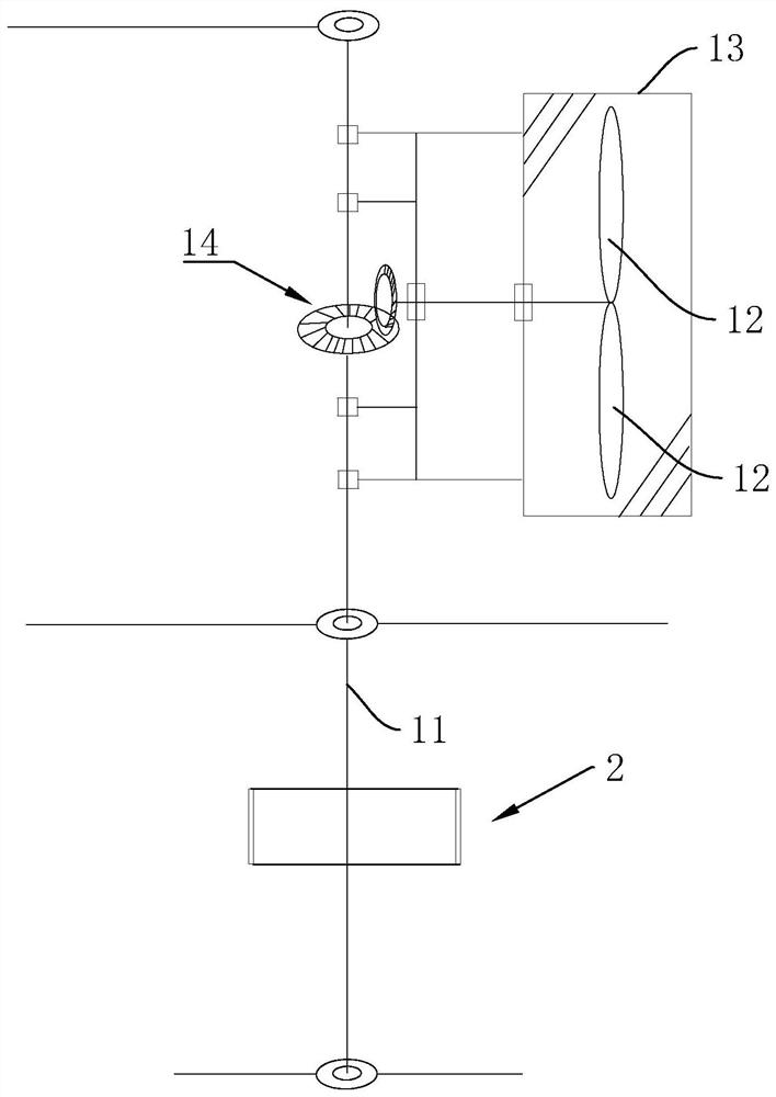
[0038] see figure 1 , the present embodiment proposes a fluid kinetic energy negative pressure power generation system, including an energy harvesting device 1, a fluid kinetic energy conversion device, and a power generation assembly. 12. The rotating shaft of the fan blade 12 is set perpendicular to the vertical shaft 11, and the fan blade 12 is covered with an energy-capturing duct 13, which can increase the wind energy. The energy-capturing duct 13 is rotationally connected with the vertical shaft 11 through a bearing, the outer wall of the bearing is connected with the energy-capturing duct 13 through a welded metal straight rod, and the inner wall of the bearing is welded and fixed to the vertical shaft 11.

[0039] The rotating shaft of the fan blade 12 runs through the energy-harvesting duct 13, and the fan blade 12 is connected to the vertical shaft 11 through the transmission assembly 14. The transmission assembly 14 includes two matching bevel gears, one of which is...

Embodiment 2

[0066] This embodiment proposes another fluid kinetic energy negative pressure power generation system, including an energy harvesting device 1, a fluid kinetic energy conversion device, and a power generation assembly. The energy harvesting device 1 includes a vertical shaft 11 arranged vertically, and a fan blade is arranged on the vertical shaft 11. 12. The rotating shaft of the fan blade 12 is set perpendicular to the vertical shaft 11, and the fan blade 12 is covered with an energy-capturing duct 13, which can increase the wind energy. The energy-capturing duct 13 is rotationally connected with the vertical shaft 11 through a bearing, the outer wall of the bearing is connected with the energy-capturing duct 13 through a welded metal straight rod, and the inner wall of the bearing is welded and fixed to the vertical shaft 11.

[0067] The rotating shaft of the fan blade 12 runs through the energy-harvesting duct 13, and the fan blade 12 is connected to the vertical shaft 11...


PUM


Abstract

The invention discloses a fluid kinetic energy negative pressure power generation system, relates to the technical field of power generation, and aims to solve the problem that existing fluid kinetic energy power generation equipment cannot stably and continuously generate power. According to the system, after energy is obtained, the energy is not immediately transmitted to an electric generator to generate electricity, and is converted into negative pressure gas to be stored, and the negative pressure gas drives the electric generator to rotate to generate electricity; and the fluid kinetic energy is stored in a negative pressure tank in a negative pressure form, and the circulation of the negative pressure gas in the product is controlled by a controller, so that the power generation rate of the product is controlled, and stable and continuous power generation is realized.

Description

technical field [0001] The invention relates to the technical field of power generation, in particular to a fluid kinetic energy negative pressure power generation system. Background technique [0002] Energy and environmental issues have become the main issues facing global sustainable development. Fluid kinetic energy such as wind energy, wave energy, and river water conservancy energy are renewable, non-polluting green energy sources that are inexhaustible and inexhaustible. Wind energy The large-scale development and utilization of fluid kinetic energy such as wave energy, river water conservancy energy, etc. will effectively reduce the use of petrochemical energy, reduce greenhouse gas emissions, protect the environment, and vigorously develop green and clean energy. It has become an important choice for governments of all countries. [0003] In today's fluid kinetic energy generation equipment such as wind turbines, the wind rotor rotates under the action of the wind, ...

Claims


Application Information

Patent Timeline
IPC IPC(8): F03D9/25F03D15/00F03D9/14F03D15/10F03D1/04F03B17/06F03B13/22F03B13/06H02K7/10H02K7/18
CPCF03D9/25F03D15/00F03D1/04F03D9/14F03D15/10F03B17/06F03B13/22H02K7/10H02K7/1807H02K7/1823H02K7/1838F03B13/06Y02E10/20Y02E10/30Y02E10/72Y02E60/16Y02E70/30
Inventor 石俊阁
Owner 石俊阁
Features
  • Generate Ideas
  • Intellectual Property
  • Life Sciences
  • Materials
  • Tech Scout
  • Unparalleled Data Quality
  • Higher Quality Content
  • 60% Fewer Hallucinations
Learn More