Test mechanism for thrust adapter
An adapter and thrust technology, applied in the aerospace field, to achieve the effect of increasing the contact surface, increasing the adjustable space, and ensuring stability
- Summary
- Abstract
- Description
- Claims
- Application Information
AI Technical Summary
Problems solved by technology
Method used
Image
Examples
Embodiment 1
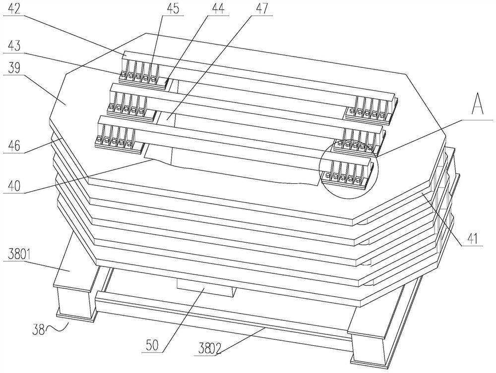
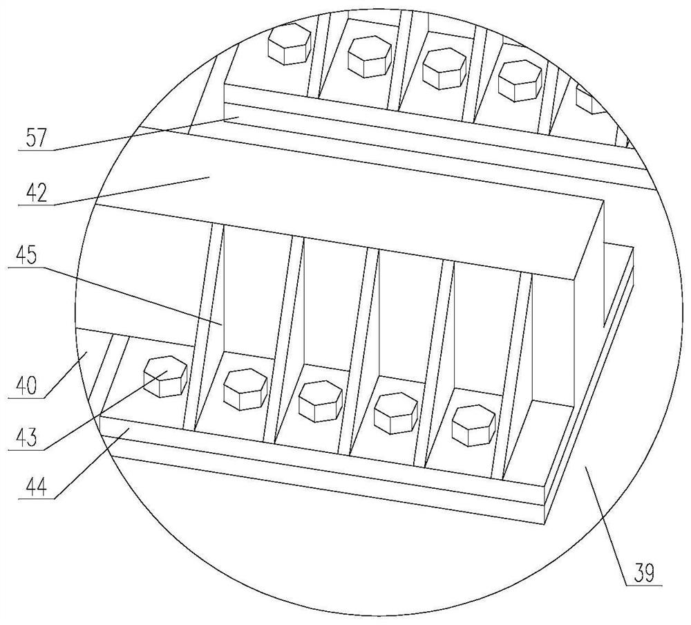
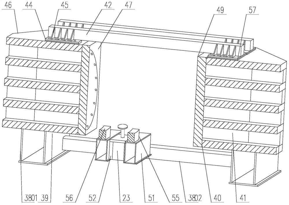
[0050] The invention is a test mechanism for a thrust adapter, comprising a bearing frame with a thrust adapter installation cavity inside, an oil cylinder bearing assembly fixed on the bottom of the bearing frame and opposite to the installation cavity, and an oil cylinder bearing assembly installed on the bearing assembly with the axis perpendicular to the horizontal plane The radial oil cylinder 23 of the oil cylinder 23, the end of the piston rod 3 of the oil cylinder 23 faces the installation cavity, and the end of the piston rod 3 is installed with a U-shaped push seat 24 through a connecting assembly, which includes a plug 7, a main bolt 22 and a washer 8 , the side of the plug 7 close to the end of the piston rod 3 protrudes outward to form a first spherical surface 37, and the plug 7 is provided with a second-level stepped through hole 25 penetrating through the first spherical surface 37, and the small diameter hole of the through hole 25 is connected to the first sphe...
Embodiment 2
[0060] This embodiment is a further description of the push seat 24 in the first embodiment.
[0061] Such as Figure 6 As shown, the push seat 24 is installed on the side of the plug 7 away from the piston rod through a mounting structure. The ear plate 29 is provided with a through hole on the ear plate 28, and the rod end of the bolt 30 passes through the through hole and is threadedly connected with the threaded hole 28, and the head of the bolt 30 is in contact with the ear plate 29.
[0062] Further, the groove bottom 32 of the U-shaped groove 31 of the push seat 24 is a cylindrical arc surface, and the axis where the center of the circle is located is perpendicular to the axis of the oil cylinder 23 .
[0063] During use, the radius of the groove bottom 32 is consistent with the outer circle of the floating thrust plate and the first test piece. When the floating thrust plate and the outer circle of the first test piece are inserted into the U-shaped groove, the outer ...
Embodiment 3
[0069] The detection of the overhanging length of the piston rod of the radial oil cylinder adopts a displacement sensor, which is specifically implemented as follows: the end of the piston rod 3 located in the cylinder barrel of the oil cylinder 23 is provided with a collection hole whose axis is parallel to the axis of the piston rod 3 35. A built-in displacement sensor 36 for collecting the moving stroke of the piston rod 3 is installed on the cylinder bottom of the oil cylinder 23. The collection end of the displacement sensor penetrates the bottom of the cylinder and is inserted into the collection hole 35, and the collection end of the sensor passes through the sealing ring and Bottom seal fit.
[0070] The displacement sensor preferably adopts a displacement sensor whose model is XST-A 4210-G50M1.
PUM
| Property | Measurement | Unit |
|---|---|---|
| Yield stress | aaaaa | aaaaa |
Abstract
Description
Claims
Application Information
 - R&D
- Intellectual Property
- Life Sciences
- Materials
- Tech Scout
- Unparalleled Data Quality
- Higher Quality Content
- 60% Fewer Hallucinations
Browse by: Latest US Patents, China's latest patents, Technical Efficacy Thesaurus, Application Domain, Technology Topic, Popular Technical Reports.
© 2025 PatSnap. All rights reserved.Legal|Privacy policy|Modern Slavery Act Transparency Statement|Sitemap|About US| Contact US: help@patsnap.com


