Self-cleaning type dust removal system of dust collector for smart home

A technology of smart home and dust removal system, applied in vacuum cleaners, suction filters, household appliances, etc., can solve the problems of fan resistance, motor damage of fans, and reduced ventilation effect of cloth bags, so as to achieve good ventilation and prevent clogging.

Active Publication Date: 2021-05-28
宁波智正伟盈信息科技有限公司
View PDF5 Cites 0 Cited by
  • Summary
  • Abstract
  • Description
  • Claims
  • Application Information

AI Technical Summary

Problems solved by technology

[0003] Among them, for the vacuum cleaners commonly used in household life, the dust or garbage is sucked into the inner bag by the negative pressure generated by the fan, but as the inhaled dust and garbage increase, the ventilation effect of the bag is greatly reduced, causing the fan to form when pumping air. Larger resistance, in severe cases, will cause damage to the motor of the fan. Therefore, after a period of use, the current vacuum cleaner needs to clean up the garbage sucked into the bag, which is time-consuming and labor-intensive. It obviously does not meet the smart design of modern smart homes. idea

Method used


Image

  • Self-cleaning type dust removal system of dust collector for smart home
  • Self-cleaning type dust removal system of dust collector for smart home
  • Self-cleaning type dust removal system of dust collector for smart home

Examples


Embodiment 1

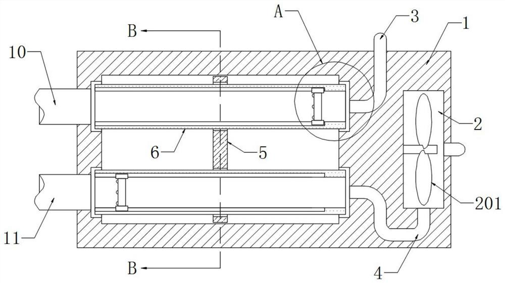
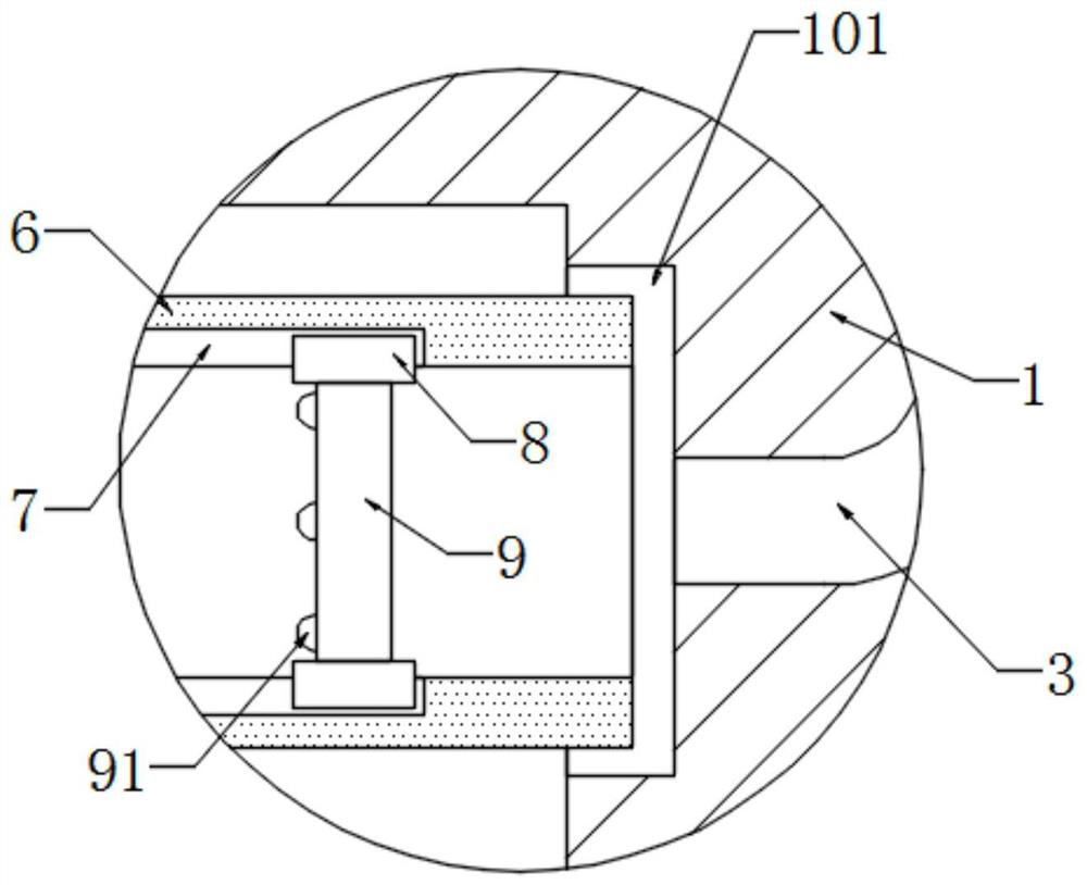
[0024] refer to Figure 1-3 , a self-cleaning dust removal system for smart household vacuum cleaners, comprising a dust collection box 1, a negative pressure tank 2 is provided on the side wall of the dust collection box 1, a negative pressure fan 201 is installed in the negative pressure tank 2, and the negative pressure tank 2 and The dust collection box 1 is connected with an air inlet pipe 3 and an air outlet pipe 4. The dust collection box 1 is rotatably connected with a rotating plate 5, and the rotating plate 5 is provided with a plurality of dust collection cylinders 6. It should be noted that the dust collection box 1 Annular grooves 101 are formed on the two opposite inner walls, and the two ends of the dust suction cylinder 6 are in close contact with the inner walls of the annular grooves 101 . There is a dust filter bag 9 slidably connected in the dust suction tube 6, and a plurality of pads 91 are fixedly connected to the side wall of the dust filter bag 9. It s...

Embodiment 2

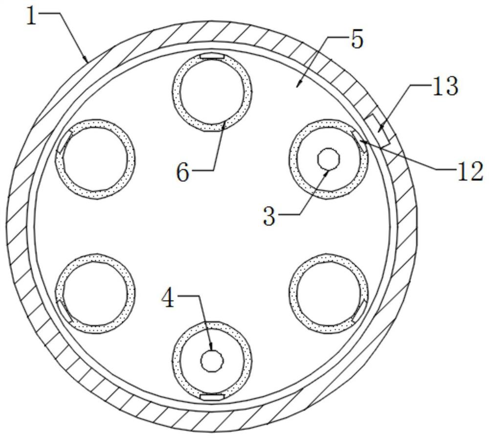
[0031] refer to Figure 4-5 , different from Embodiment 1, the side wall of the dust outlet pipe 11 is provided with a plurality of extrusion grooves 15, and the two opposite inner walls of the extrusion groove 15 are elastically connected by a conductive spring 16, and the guide block 8 is made of a magnetic material. The vacuum tube 6 is embedded with multiple groups of helical coils 14 electrically connected to the conductive springs 16. Specifically, each group of helical coils 14 is separated by a certain distance, and when the guide block 8 moves in the guide groove 7, it will pass through each group in turn. Helical coils 14, so that each group of helical coils 14 can be energized once in turn. In addition, each conductive spring 16 is only electrically connected with one helical coil 14. Therefore, during the movement of the guide block 8, each conductive spring 16 can be sequentially energized. Stretch once. The outer wall of the dust outlet pipe 11 is made of hard p...


PUM


Abstract

The invention discloses a self-cleaning type dust removal system of a dust collector for smart home.The system comprises a dust suction box, a negative pressure groove is formed in the side wall of the dust suction box, a negative pressure fan is installed in the negative pressure groove, the negative pressure groove and the dust suction box are communicated with an air inlet pipe and an air outlet pipe, a rotating plate is rotationally connected into the dust suction box, a plurality of dust collection barrels are arranged on the rotating plate in a penetrating mode, dust filtering bags are connected into the dust collection barrels in a sliding mode, a dust inlet pipe and a dust outlet pipe which are communicated with the interior of the dust collection box are installed on the side wall of the dust collection box, and a control device for controlling the rotating plate to rotate is installed in the dust collection box. The dust filter bags are pushed to move through air exhausted by the negative pressure fan, on one hand, garbage and dust in the dust collection barrels can be guided out through the dust outlet pipe; and on the other hand, high-speed airflow blown out by the negative pressure fan cleans the dust filter bag, good air permeability of the dust filter bag is kept, the self-cleaning effect on the dust filter bag can be achieved, manual maintenance is not needed, and the intelligent requirements of modern home are met.

Description

technical field [0001] The invention relates to the technical field of smart home related equipment, in particular to a self-cleaning dust removal system for a smart home vacuum cleaner. Background technique [0002] With the improvement of people's living standards, people's requirements for household equipment are getting higher and higher, and the equipment is often required to be more intelligent. [0003] Among them, for the vacuum cleaners commonly used in household life, the dust or garbage is sucked into the inner bag by the negative pressure generated by the fan, but as the inhaled dust and garbage increase, the ventilation effect of the bag is greatly reduced, causing the fan to form when pumping air. Larger resistance, in severe cases, will cause damage to the motor of the fan. Therefore, after a period of use, the current vacuum cleaner needs to clean up the garbage sucked into the bag, which is time-consuming and labor-intensive. It obviously does not meet the s...

Claims


Application Information

Patent Timeline
Patent Type & Authority Applications(China)
IPC IPC(8): A47L9/14
CPCA47L9/149A47L9/14
Inventor 王同军
Owner 宁波智正伟盈信息科技有限公司
Why Eureka
Try Eureka